Back to blog
Article
Mobile Toilet Water and Electricity Layout Diagram
Admin October 09, 2026
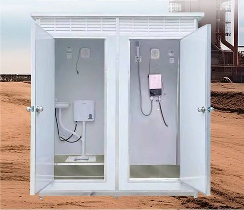
Currently, no detailed diagrammatic information directly related to the 'Mobile Toilet Water and Electricity Layout Diagram' has been found, but design references can be provided by combining key points of bathroom water and electricity layout. The specific layout should be drawn by a professional plumber and electrician based on the actual situation.

I. Toilet Relocation and Water-Electricity Adaptation
- Interlayer Drainage Relocation: If a toilet relocation device is used, the floor slab needs to be raised to embed the pipes. The relocation distance is recommended not to exceed 2 meters, and a drainage slope (usually 2%-3%) should be ensured to avoid blockage. Water and electricity pipelines should avoid the relocation path to prevent conflicts during later maintenance.
- Floor Drain to Wall Drain Conversion: The toilet can only be relocated to the adjacent wall of the sewage riser. A false wall needs to be built to hide the pipes, and a niche space should be reserved. Water and electricity pre-embedding should cooperate with the wall drain conversion, such as pre-embedding cold and hot water pipes and a smart toilet socket (30cm from the ground, lower than the water tank) in the false wall.
- Sunken Bathroom Relocation: The length or direction of the pipes can be directly adjusted, and the water and electricity layout should adapt to the new pipe direction. For example, if the toilet is relocated close to the shower area, the bath heater circuit should avoid the damp area and use a splash-proof socket instead.
II. Core Water-Electricity Configuration in the Toilet Area
- Space Dimensions: The width of the toilet area is recommended to be 80-90cm to ensure comfort. If installing a wall-mounted toilet, the water tank frame and water-electricity interfaces should be pre-embedded in advance.
- Sockets and Equipment:
- Smart Toilet Socket: Installed on the side, 30cm from the ground, lower than the water tank, and equipped with a waterproof box.
- Night Light Control: An infrared induction switch can be installed, and the circuit should be laid independently to avoid interference with other equipment.
- Toilet Spray Gun: Reserve a cold water interface, positioned close to the right side of the toilet (based on right-hand usage habits), with a height of 40-50cm from the ground.
- Bath Heater Installation: Avoid installing it directly above the shower area to prevent steam from affecting the equipment's lifespan. It is recommended to install it on the top of the toilet area, with a 4-square dedicated line and a leakage protector (RCD), and the switch should be placed outside the door.
III. Concealed Works: Drainage and Electrical Safety
- Drainage Logic:
- Wall Drain Downpipe: Pre-embed a 50mm pipe diameter with a 2% slope. The outlet position should be lower than the basin inlet and equipped with an odor-proof sealing ring.
- Floor Drain Design: Adopt a 'square spiral' layout with a slope adjusted to 3%. The depth of the water trap should be ≥50mm to prevent odor.
- Electrical Safety:
- Smart Toilet Socket: In addition to waterproof requirements, it should be kept more than 1.5 meters away from the shower area socket.
- Electric Water Heater Circuit: Run a separate 4-square dedicated line, equipped with a 40A RCD. The equipotential terminal must be reliably grounded to reduce the risk of electric shock.
If a specific layout diagram is needed, it is recommended to have a professional plumber and electrician measure on-site according to the bathroom structure (such as same-floor drainage or interlayer drainage), toilet relocation method, and equipment installation requirements to ensure compliance with regulations and practicality.
Related