Mobile Toilet Management System Drawings
Currently, there is no complete publicly available information directly targeting the 'drawings of the mobile toilet management system', but design references can be obtained through the following relevant types of drawings:
1. Pipeline Framework Layout Design Drawings
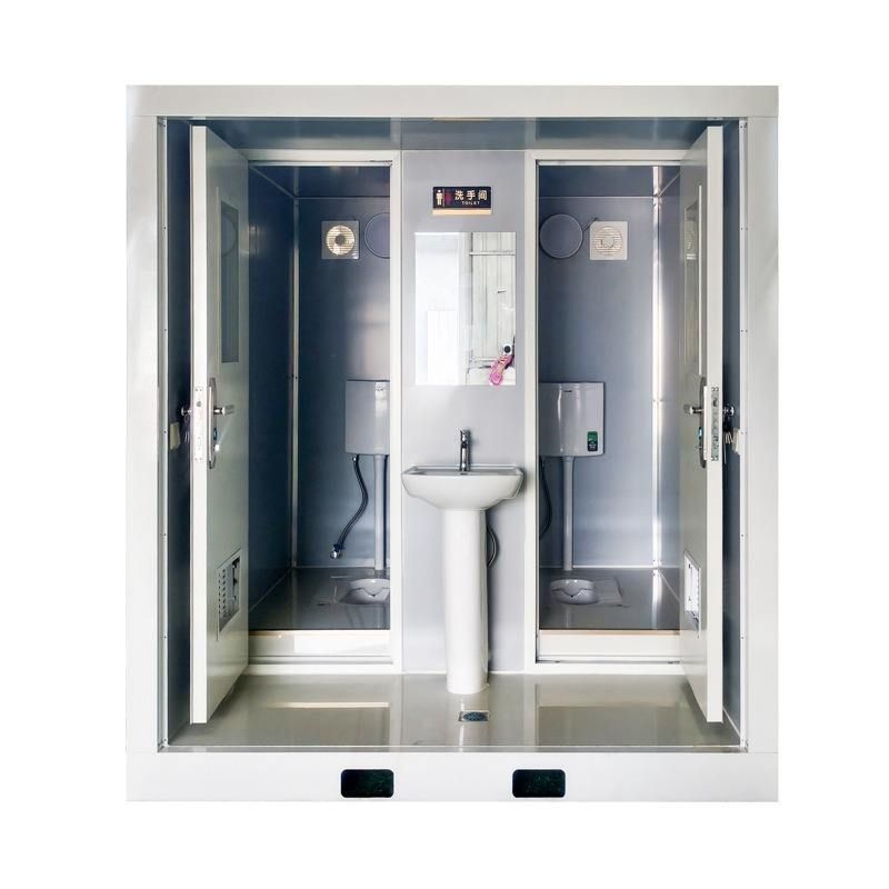
The pipeline system of a mobile toilet is a core functional module, and its design drawings are usually presented in the form of SolidWorks 3D models, including detailed component files of the pipeline framework. For example, stainless steel pipes, as the main pipelines, need to be labeled with pipe diameters, wall thicknesses, and material standards; joints and elbows need to specify connection methods (such as threaded connections, welding) and angle parameters. These drawings can visually display the pipeline routing, spatial layout, and component assembly relationships, providing structural references for the maintenance of the management system.
2. Modular Toilet Overall Design Drawings
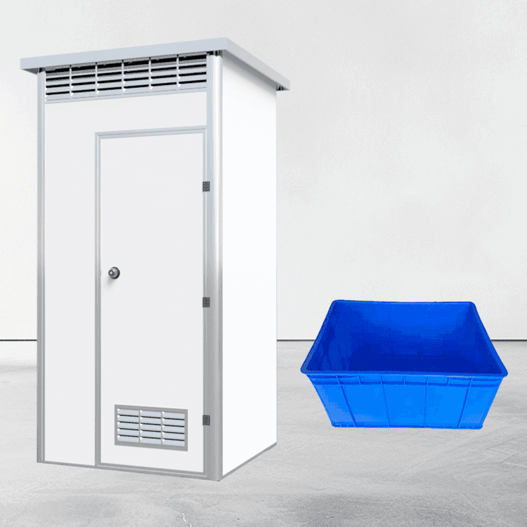
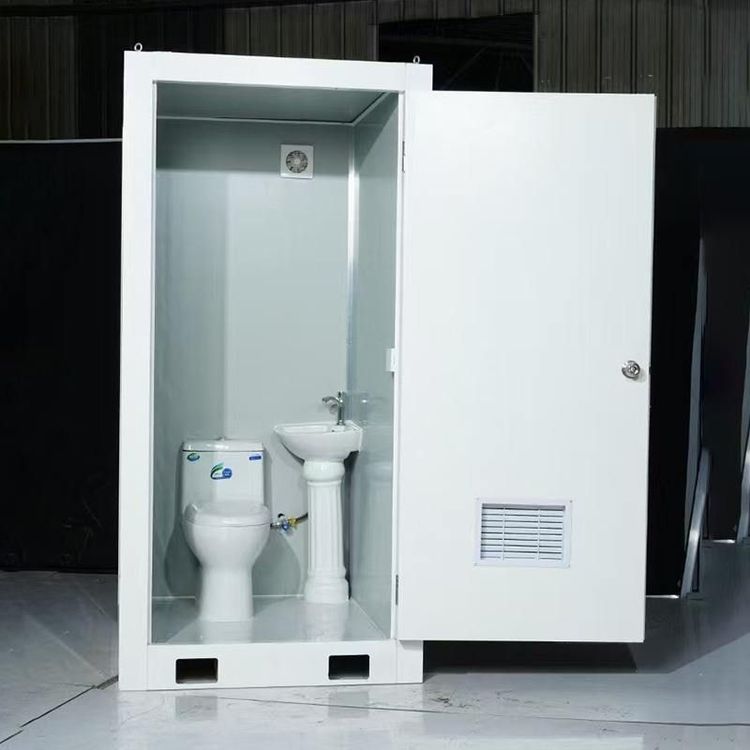
Modular design is a common form for mobile toilets. The drawings include isometric views, side views, top views, and front views, comprehensively presenting the spatial structure of the toilet. For example, the design of enclosed cabinets needs to be labeled with dimensions, materials (such as fiberglass-reinforced plastic or stainless steel), and surface treatment processes; mobile wheelsets need to specify load-bearing capacities, steering mechanisms, and fixing methods. In addition, the integrated design of the toilet base and water supply and drainage interfaces needs to be labeled with installation heights, slopes, and sealing requirements to ensure compatibility between the management system and the main structure.
3. Processing and Configuration List Drawings
The information on mobile toilets usually includes rendering images, CAD processing drawings, configuration lists, and material lists. Among them, CAD processing drawings need to be detailed down to the part level, such as pipeline cutting lengths, hole positions, and welding locations; the configuration list needs to list the models, specifications, and supplier information of all components (such as water pumps, valves, sensors); the material list needs to indicate environmental protection standards (such as waterproof ratings, corrosion resistance). These drawings provide detailed bases for the replacement of spare parts and troubleshooting in the management system.
4. Application Scenarios and Precautions for Drawings
The above drawings can assist in the design of the management system, but the following points need to be noted:
- Drawing version: Ensure that the latest version of the design documents is referenced to avoid the failure of the management plan due to structural optimization.
- Standard matching: The pipeline materials and interface specifications need to comply with local sanitation and environmental protection standards.
- Dynamic updating: The management system needs to adjust the drawing parameters according to actual usage feedback (such as water consumption, failure rates).
If complete drawings of the management system are required, it is recommended to contact the equipment manufacturer or design unit to obtain customized solutions.