Mobile Toilet Circuit Diagram and Principle
The circuit diagram and principle of mobile toilets mainly involve three core modules: power supply management, automatic flushing, and intelligent device control. The design logic revolves around functional requirements and scenario adaptation, as detailed below:

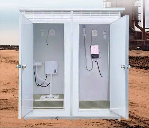
1. Power Supply Architecture for Mobile Toilets in Expressway Service Areas: Centralized Control and Low-Voltage DC Power In this scenario, the mobile toilet connects to a 220V AC power supply through a controller, which is then converted to 12V or 24V DC power via an AC-DC module to supply internal devices. Core devices include presence/absence indicators, ceiling speakers, exhaust fans, toilet occupancy sensors, lighting, and smart locks for partition doors, all connected to the controller via IO signals for centralized management. For example, when the occupancy sensor detects someone, the controller activates the lighting and exhaust fan; they automatically turn off when unoccupied to save energy. The low-voltage DC power design reduces the risk of electric shock, meets the electrical safety requirements of mobile scenarios, and avoids line redundancy caused by independent power supplies for each device through centralized controller scheduling.
2. Automatic Flushing Controller Circuit for Public Toilets: Timer Circuit and Photosensitive Adjustment The automatic flushing function relies on a pulse signal oscillator composed of an NE555 timer circuit, with the following core logic:
- Power Supply Circuit: Transformer T steps down the 220V AC power, which is then rectified by VD1-VD4, stabilized by VD5, and filtered by C1 to output 12V DC power for the circuit.
- Charge/Discharge Control: The photosensitive resistor R2 dynamically adjusts its resistance based on light intensity (approximately 5kΩ during the day and 5MΩ at night), altering the discharge time of capacitor C2 to control the on/off cycle of the solenoid valve. The flushing interval is about 15 minutes during the day and extended to 1 hour at night, balancing hygiene needs with water conservation.
- Manual Function: The solenoid valve can be directly triggered to flush water via switch S as a supplement to the automatic mode for special circumstances.
3. Smart Toilet Seat Circuit Control: Multi-Module Collaboration and Precise Regulation The circuit of the smart toilet seat is divided into three parts: water circuit, circuit control, and mechanism heating:
- Water Circuit: The pressure-regulating valve assembly (solenoid valve + pressure-regulating valve) adjusts the water flow pressure, while the flow meter monitors the flow rate in real-time and feeds it back to the MCU (microcontrol unit). The instant heating assembly (ceramic heating tube + temperature sensor) stabilizes the water temperature at 40℃ ± 1℃ within 15 seconds, with a fluctuation ≤ 2℃, ensuring comfort during use.
- Circuit Control: The MCU adjusts the heating power and reversing valve operation based on sensor signals (such as water temperature, flow rate, and user operations) to achieve functions like warm water washing and warm air drying. For example, when the user selects the "buttock washing" mode, the MCU controls the water flow direction, temperature, and nozzle position to provide personalized services.
The above circuit designs all focus on functional realization while considering safety, energy efficiency, and user experience, serving as key technical supports for the intelligent and efficient operation of mobile toilets.