Key Facts About Fully Automatic Glass Roofs
When designing glass skylights supported by glass fins, safety is the primary concern—determined by the nature of glass itself. This material can experience varying degrees of spontaneous breakage during use, which must be fully considered in design. If a supporting glass fin is damaged, the entire support beam must still provide sufficient bearing capacity to ensure glass panels do not fall in the short term. To ensure safety, the following issues must be considered when designing point-supported fully automatic glass roofs with glass-beam support structures:
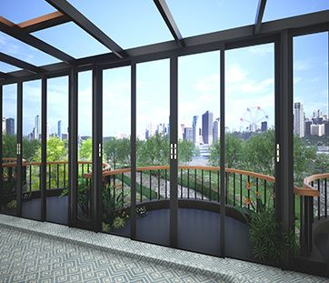
1) Glass fins of glass skylights should preferably use triple-layer glass. Support beams should be formed through lamination to ensure integrity.
2) Connections between glass beams and panel glass of fully automatic glass skylights should use perforated spider fittings and countersunk bolts to improve connection reliability.
3) The span of glass beams in glass skylights should not exceed 2.00 m. Minimize perforations on glass beams and joints between beams.
4) When designing glass skylights, support points at both ends of glass beams should be hinged. When panels deform under load, support points at both ends of glass beams can rotate freely.
5) For glass beams connected with metal fittings, connector thickness should not be less than 6 mm and bolt diameter not less than 8 mm.
There are two main connection methods between glass panels and support structures in point-supported fully automatic glass roofs: one is drilling holes in the glass panel, fixing the surface with stainless steel countersunk fittings, and connecting to the support structure via spider fittings—called perforated connection; the other uses stainless steel splice plates at panel edges and gaps between panels, then connects panels to the support structure via spider fittings or connectors—called splice-plate connection.
Issues to consider for splice-plate connections in fully automatic glass roofs:
1) Splice plates on glass panels can be divided into plates at intersections of multiple panels and plates along sealant lines between two panels. Cross-type splice plates are fixed at corners of flat glass; sealant-line splice plates are fixed at panel edges.
2) There should be sufficient gap between metal splice plates and glass panels to allow glass deformation under in-plane loads.
3) When facing glass is laminated insulating tempered glass, splice plates can clamp the entire glass assembly or only clamp the two laminated layers below the insulating glass, with the upper glass bonded using a hidden frame.
Air tightness and water tightness of point-supported fully automatic glass roofs rely mainly on sealant joints between panels. When setting sealant joint width to ensure proper function under various conditions, several factors must be considered:
1) In-plane dimensional changes of glass panels due to hot and cold temperature variation (±80°C);
- Dimensional and shape changes of flat glass in glass skylights under wind load, snow load, earthquake, self-weight, maintenance load, and other loads perpendicular to the glass plane;
3) Differences in laminated panel dimensions and facing-glass diagonal differences from glass processing (tempering, hollowing, laminating, drilling, etc.);
4) Sealant joint width for glass skylights should account for installation tolerances during panel and accessory installation.