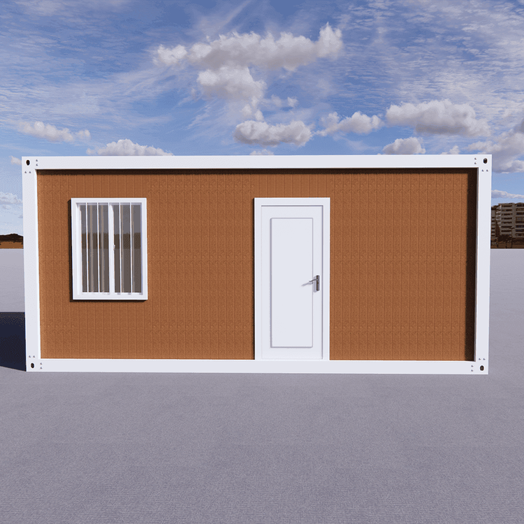
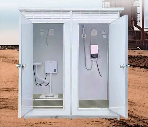
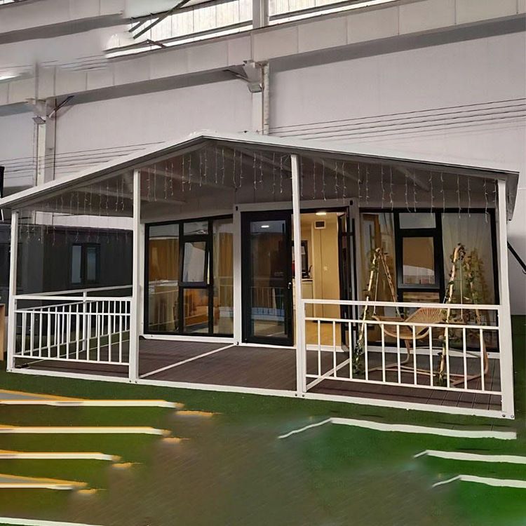
Container House Frame Design Drawing
The structural drawings of the two-story container house provided by Mufeng Network cover the key elements of container house frame design and can serve as a detailed reference for design purposes. The following provides an explanation from four aspects: the core content of the design drawings, structural material specifications, types of drawings, and design considerations.

I. Core Structural Elements
The design of a container house frame must clearly define the basic structures such as columns, keels, wall panels, and door and window openings. According to the drawings from Mufeng Network, columns typically use high-strength steel (such as Q345B), with specifications determined based on the number of floors, span, and load calculations of the house. For example, columns for a two-story house may use square tubes measuring 120mm×120mm×6mm to ensure vertical load-bearing capacity. The arrangement of top and bottom keels should form a grid support system, with top keel spacing generally controlled within 600mm, and bottom keels must be firmly connected to the ground foundation to prevent settlement. Wall panel design should balance insulation and strength, commonly using color-coated steel sandwich panels (thickness 50-100mm) filled with polystyrene or rock wool internally. Door and window openings should reserve structural reinforcement frames to avoid local stress concentration.
II. Structural Material Specifications
Material selection directly affects the safety and durability of the house. Columns and keel steel must comply with the "Steel Structure Design Standard" (GB50017), with a tensile strength of no less than 470MPa. The thickness of color-coated steel for wall panels is typically 0.5-1.0mm, with a zinc coating of at least 275g/㎡ for corrosion resistance. Door and window frames are recommended to use thermal-break aluminum alloy, paired with insulated glass (5mm+12A+5mm) to enhance thermal insulation performance. Connectors (such as bolts and corner brackets) should use 8.8-grade high-strength bolts to ensure joint rigidity. If the house is located in an earthquake zone, additional diagonal braces or seismic supports are required, with material specifications verified through structural calculation software.
III. Types of Drawings and Their Functions
The drawings provided by Mufeng Network include three types:
- Floor Plans: These show the layout of each floor, marking the positions and dimensions of walls, doors, and windows. For example, the first-floor plan should clearly define the partitions for the living room and kitchen, while the second floor should mark the positions of bedrooms and stairs.
- Elevation Drawings: These present the exterior appearance of the house, marking heights, door and window heights, and the positions of decorative elements such as awnings and sunshades.
- Section Drawings: These cut through key parts (such as walls and stairs) to show the internal structural layers, for example, marking the thickness of color-coated steel, keels, insulation layers, and connection methods in wall sections.
IV. Design Considerations
When designing, it is essential to focus on load distribution (e.g., the live load on the second-floor surface should be taken as 2.0kN/㎡), corrosion protection (steel should be sandblasted and painted with epoxy zinc-rich primer), and modular assembly (the standard size of containers is 6058mm×2438mm×2896mm, and the design should be compatible with standard modules). Additionally, the drawings should indicate the allowable construction error range (e.g., the verticality deviation of keel installation should be ≤3mm) and include a material list and detailed node drawings to ensure construction feasibility.