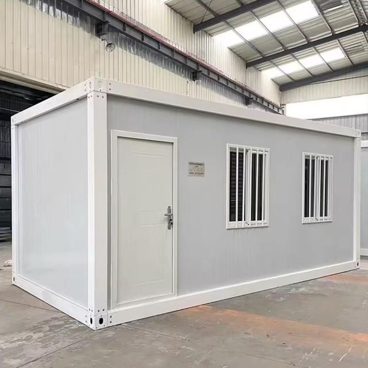
Connection Diagram of Assembly Prefabricated Houses
The connection diagram of assembly prefabricated houses mainly involves various connection methods and detailed structural drawings. The following are explanations of key connection methods:

Grouting Connection
Sleeve Grouting Connection
- Full Grouting Sleeve Connection: Finished sleeves are pre-embedded in prefabricated concrete components. After inserting steel bars at both ends, grout is injected to achieve the connection. The core components include connecting steel bars, grout outlet holes, sleeves, grout injection holes, and grout. After the grout hardens, it forms an integral whole, ensuring the transfer of mechanical properties of the steel bars.
- Half Grouting Sleeve Connection: The upper inner part of the sleeve is threaded, and the end of the connecting steel bar is also threaded. Mechanical interlocking connection is achieved through the threads. This method combines the advantages of grouting and mechanical connections and is suitable for scenarios with high requirements for connection strength.
Spiral Stirrup Grout Anchor Lap Connection
The lap area of steel bars in the reserved duct is reinforced with spiral stirrups. Two lap steel bars are wrapped with spiral stirrups on the outer circle, and then grout is injected. The spiral stirrups can restrain the lateral deformation of the concrete and improve the shear bearing capacity of the lap area, making it suitable for the connection of large-diameter steel bars.Corrugated Pipe Grout Anchor Lap Connection
Corrugated pipes are used as the formwork for the reserved duct, and then steel bars are inserted and grouted. The corrugated structure of the corrugated pipes can enhance the bond strength with the grout and also restrain the displacement of the steel bars, making it suitable for the steel bar connection of vertical components (such as shear walls).
Steel Connection Box Connection
Adjacent partition wall panels are connected through pre-embedded steel connection boxes on the sides. The cavity of the connection box is composed of left and right reinforcing steel bars and bolt holes. The bolt holes are used for installing fastening bolts, and the bolt sleeves are welded to the reinforcing steel bars inside the partition wall panels. This method transfers loads through mechanical connections and has the advantages of convenient installation and disassembly, making it suitable for the connection of non-load-bearing partition walls.
Example Illustrations of Sleeve Grouting Connections
The technical documents include illustrations of sleeve grouting connections for prefabricated concrete shear walls, frame columns, frame beams, and other components. For example, the connection of shear walls needs to show the positioning of the sleeves, the insertion depth of the steel bars, and the arrangement of the grout holes; the connection of frame beams needs to clarify the对接 (docking, here it means the way of connection) method between the beam-end steel bars and the sleeves. Specific illustrations can refer to four series of atlases of standard prefabricated concrete components for assembly-type residential buildings, such as the "Standard Base Plate of Prestressed Concrete Steel Pipe Truss Composite Slabs", which contain detailed structural nodes and technical descriptions.
Reference Recommendations
Since the connection diagram involves professional structural details, it is recommended to conduct in-depth design in combination with standard atlases (such as the "Technical Specification for Assembly-type Concrete Structures" JGJ 1-2014) and design software (such as Revit and Tekla Structures) to ensure that the connection nodes meet requirements for earthquake resistance and durability.