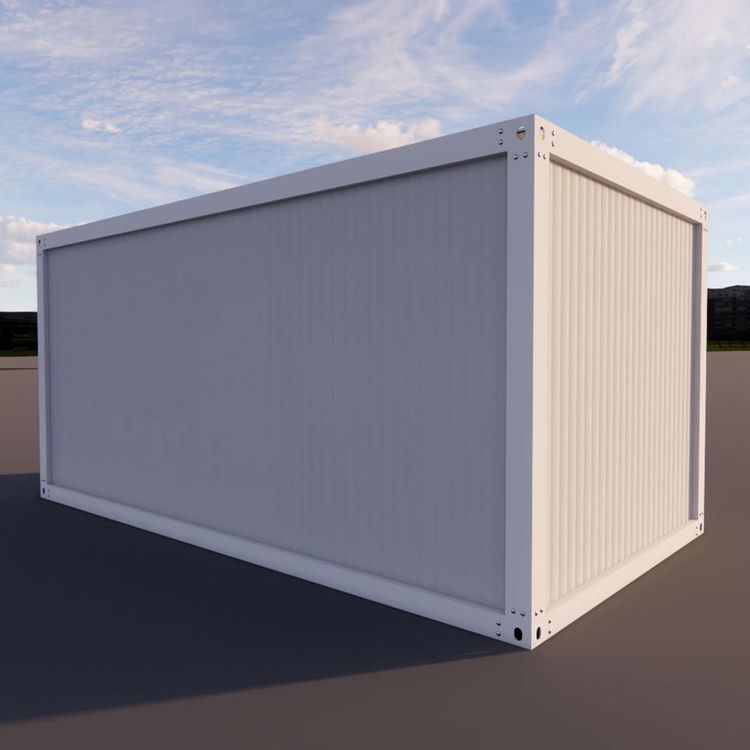
Container House Steel Frame Anatomy: Structure & How It Works
The anatomical structure of the Container House Steel Frame revolves around the transfer of forces and the collaborative action of components. Through the division of labor among flexural members, compression members, and connectors, combined with precise structural design and process control, structural safety and functional balance are achieved.

I. Types and Functions of Core Components
Flexural Members
Primarily steel beams, often with an I-shaped cross-section, where materials are concentrated in the top and bottom flanges to resist tensile and compressive stresses generated by bending, while the web mainly bears shear forces. For example, under vertical loads, the floor slab transfers the load to the steel beam, with the flanges dispersing stress through deformation and the web maintaining structural stability through shear deformation.Compression Members
Steel columns are typical compression members, commonly with box-shaped or wide-flange H-shaped cross-sections, needing to withstand both axial pressure and bending moments simultaneously. Under horizontal loads (such as wind pressure or earthquakes), steel columns transfer forces to the foundation through cross-sectional deformation, while requiring structural design (such as stiffeners) to prevent local buckling.Connectors
Divided into welded rigid joints (transmitting bending moments) and high-strength bolted semi-rigid/pinned joints (transmitting shear forces). The arrangement of joints directly affects the overall stiffness distribution. For example, in areas with significant temperature changes, pinned joints are used to accommodate the thermal expansion and contraction of steel, preventing instability caused by temperature stresses.
II. Force Transfer Paths
Vertical loads are directly borne by steel columns or frames, with walls not participating in load-bearing; horizontal loads are transferred through the floor slab to the steel beams, then to the steel columns, and finally into the foundation. This path allows for flexible internal space division but requires extremely high precision in joint connections. For example, in areas with large temperature differences like Baicheng, structural design (such as setting expansion joints) is needed to accommodate the thermal expansion and contraction of steel, preventing joint damage from repeated temperature stresses.
III. Key Structural Designs
- Foundation Connection: The bottom of steel columns is fixed to the concrete foundation through embedded anchor bolts, with the foundation depth exceeding the thickness of the frost layer to prevent uneven uplift from frost heave forces.
- Stiffness and Flexibility Allocation: Horizontal lateral displacement is adjusted by setting up bracing systems or shear walls to avoid structural over-stiffness leading to brittle fracture or over-flexibility affecting comfort.
- Separation of Enclosure System: The enclosure wall is separated from the main structure, with steel members wrapped in insulation materials on the outside to address thermal bridge effects and a vapor barrier layer on the inside; exterior wall cladding or infill walls serve only as decoration and wind protection, not load-bearing.
- Fire Protection and Pipeline Layout: Steel members are coated with fire-resistant paint or wrapped in fire-resistant boards, with thickness calculated based on cross-sectional dimensions and fire resistance limits; water and electricity pipelines are laid in the ceiling of the floor slab or the cavity of wall studs to avoid weakening the cross-section of steel members.
IV. Key Manufacturing Process Points
- Lofting and Marking: Consideration must be given to welding shrinkage, cutting allowances, and assembly gaps, with compensation amounts determined through empirical formulas or process trials.
- Assembly and Welding: Use jigs and fixtures to ensure the precision of component cross-sections, control heat input (such as limiting welding current, voltage, and speed) to reduce hardness changes in the heat-affected zone, and perform ultrasonic or radiographic testing after welding to detect internal defects.
- Hole Making Precision: Hole position deviations must be controlled to the millimeter level to ensure free insertion of high-strength bolts, avoiding forced hole enlargement that could damage the hole wall.