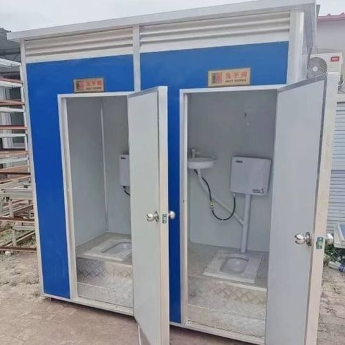
Anhui Mobile Smart Toilet Installation
The installation of Anhui Mobile Smart Toilets should follow the following specifications and steps:
I. System Wiring Specifications
- Device Access Limitations: The number of polling devices on a single bus should be ≤64, and the number of devices on a single serial port should be ≤124 to avoid communication overload.
- Distance and Resistance: When wiring exceeds 30 meters, 120Ω terminal resistors should be connected at both ends. When the total bus length exceeds 200 meters, the baud rate should be ≤9600bps.
- Cable Selection: It is recommended to use 4×0.5mm twisted-pair shielded cables (impedance 120Ω), with the shielding layer grounded at both ends to reduce interference.
- Wiring Inspection: After completion, test the line continuity resistance (to ensure no open circuits) and insulation (to ensure no damage or short circuits).
- Wiring Principles: Strictly follow the A-A, B-B, GND-GND correspondence. If communication abnormalities occur, check the wiring first for correctness.
II. Terminal Resistor Installation
Terminal resistors (120Ω) should be installed at the starting end and the farthest position of the RS485 bus. If the host is not at both ends, resistors should be soldered on the corresponding sub-devices to ensure stable signal transmission.
III. Host Installation Requirements
- Protective Measures: The host should be installed in a dedicated equipment box that is waterproof, sun-proof, and dustproof.
- Power Supply Specifications: Use the original factory-standard adapter for power supply. Do not supply power to other devices to avoid overload.
- HDMI Cable Usage: If the HDMI cable length exceeds 10 meters, choose a well-known brand cable. After powering off, wait for the blue light to go out (3-5 seconds) before powering on again to prevent device damage.
IV. Sensor Installation Points
- Protection and Power Supply: Sensors should be waterproof, sun-proof, and dustproof. For outdoor locations, install a protective casing. Use DC 12V centralized power supply, with the load matching the device.
- Initialization Settings: After installation, power off and restart the sensor (ensure no people/objects are blocking it), and the device will automatically learn the detection distance.
- Address Code Matching: Set the sensor address code according to the squat position coding diagram to ensure accurate data transmission.
V. Smart Partition Door Lock Installation
- Waterproofing: The door lock should be waterproof, and a baffle should be installed at water-splashing positions.
- Power Supply Method: The electric model uses DC 12V centralized power supply, while the mechanical model does not require power supply but needs to be adapted to the door thickness and lock hole size.
VI. Door Header Screen Installation Specifications
- Protection Level: Choose devices with an IP65 or higher protection level to ensure waterproofing and sun protection.
- Power Supply and Wiring: Use DC 12V centralized power supply, with the total power matching. The network cable should have 2 or more wire cores connected in parallel, and the power cable is recommended to be RVV2×1.0mm.
VII. Prefabricated 5G Smart Station
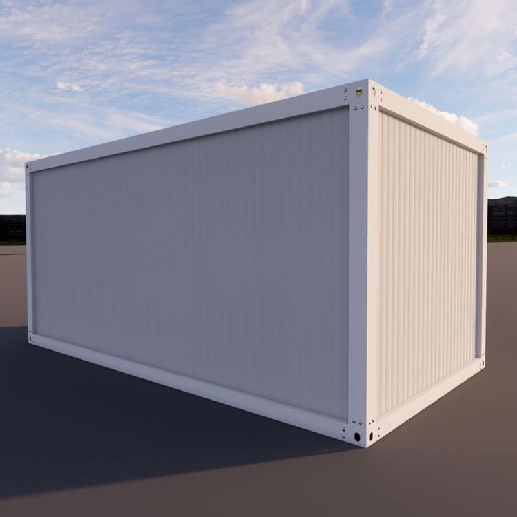
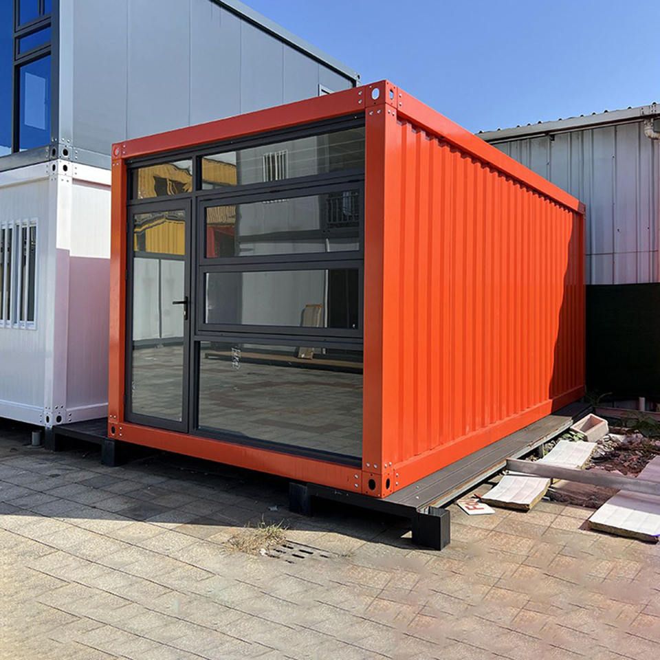
The Anhui Nanhu Scenic Area project uses prefabricated modular boxes for construction, which are prefabricated in the factory and quickly assembled on-site, resulting in a short construction period and minimal environmental damage. The station integrates a smart monitoring system for real-time equipment control and simplified later-stage maintenance.
VIII. Door Lock Sensor Wiring
Detect the occupied/unoccupied state through the door lock switch status. Before wiring, check if the door screen is normal. Connect the power supply, door screen, and sensor wires of the same color, and wrap them with protective tape to ensure safety.