Lifting Plan for Prefabricated Concrete Houses
The lifting plan for prefabricated concrete houses should cover three core aspects: project overview, construction preparation, and construction techniques. The specific content is as follows:

I. Project Overview
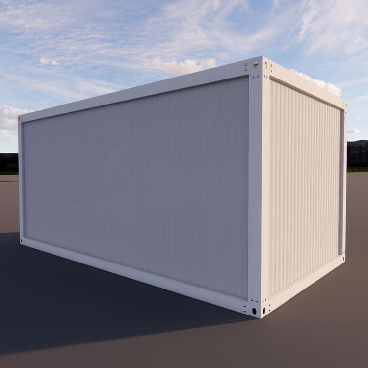
It is necessary to clarify the project type (such as industrial warehouse buildings or prefabricated villas), structural form (prefabricated reinforced concrete or fully prefabricated assembly system), building scale (area per building, number of floors, height), component parameters (thickness and self-weight of walls/roofs), and key dimensions (plan dimensions, eave height). For example, an industrial warehouse building may have a single-building area of 180㎡ and a self-weight of 65t; a prefabricated villa may have a total building area of 380㎡, including three major categories of prefabricated load-bearing components, enclosure components, and functional components.
II. Construction Preparation
Technical Preparation
- Drawing Review: Focus on verifying deviations in foundation axes and embedded part positions, elevation errors, and plan position deviations.
- Special Plan Preparation: Include a lifting layout plan (marking crane station positions, travel routes, component stacking areas, and warning zones), a four-point lifting method design (Q345B steel lifting rings at the top four corners with a burial depth of ≥200mm), and stability calculations (overturning moment safety factor K ≥ 1.5, lifting rigging safety factor ≥ 8 times).
- Technical Disclosure: Implement a three-level disclosure system, forming written records and obtaining signatures for confirmation.
- Detailed Design: Complete component disassembly drawings, lifting sequence diagrams, and node detail drawings. Simulate the lifting process through BIM modeling to identify clashes in advance.
On-site Preparation
- Site Treatment: Harden the lifting area and transportation channels (300mm graded gravel base layer + 200mm C30 concrete with a two-way steel mesh), and set a 3% drainage slope and collection wells.
- Component Stacking: Store main components separately, with bottom pads corresponding to lifting points; stack auxiliary modules ≤ 2 layers high, with wooden boards for cushioning between layers, and mark with numbers, weights, and lifting sequences.
- Foundation Acceptance: Ensure concrete strength reaches 100% of the design value, with a surface flatness deviation of ≤5mm/2m and an elevation deviation of ±3mm for embedded parts.
Material Preparation
- Component Supply: Provide demand plans and loading sequence tables to the factory 7 days in advance to ensure direct lifting on-site and avoid secondary handling.
- Equipment Selection: Choose tower cranes based on component weights (e.g., a 6517B-10 type with a 30-meter boom and a maximum lifting capacity of 6 tons for the heaviest component of 5.5t).
- Tools and Materials: Prepare steel beams, diagonal braces, lifting claws, cement self-tapping screws, etc., and calculate quantities and customization cycles in advance.
III. Construction Techniques
Component Transportation: Select vehicles based on size and weight, and secure components firmly to prevent displacement.
Component Lifting
- General Requirements: Check the integrity of equipment and lifting rigging, and select a matching lifting system (e.g., 2 HRB400E lifting rings for prefabricated columns, 6-point adjustable lifting rigging for composite beams).
- Sub-item Points:
- Composite floor slabs: Use 6 hooks for lengths > 4m and 4 hooks for lengths ≤ 4m, with lifting points symmetrically arranged.
- Special-shaped components (e.g., L-shaped corner wall panels): Adopt an 8-point lifting system with a lifting angle of ≤45°.
Component Connection: Weld or bolt connect according to design requirements, ensuring the connection area is clean and dry, and conduct acceptance after completion.
Alignment and Reinforcement: Use a level and plumb bob to correct position dimensions and reinforce according to design (e.g., set diagonal braces for exterior wall panels).