
Prefabricated Housing Component Drawings
Prefabricated housing component drawings are a collection of drawings that showcase the design, construction, and installation details of various prefabricated components in prefabricated buildings. Their core content covers component types, construction details, connection methods, and installation positioning information. The following provides an explanation from three aspects: component classification, drawing composition, and technical characteristics.
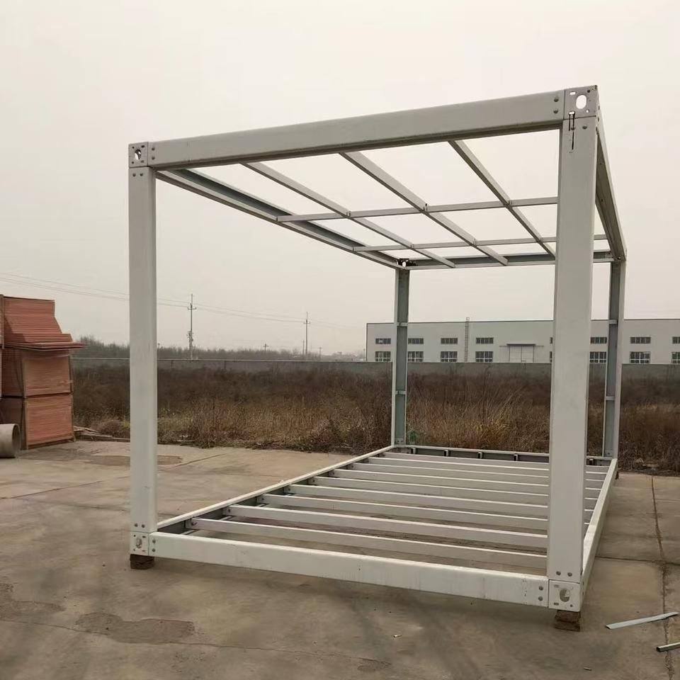
I. Main Types of Prefabricated Components
- Horizontal Components: These include prefabricated floor slabs (solid slabs, hollow slabs, composite slabs, balconies), prefabricated beams (solid beams, composite beams, U-shaped beams), and prefabricated stairs (stair flights, landings). Taking prefabricated composite slabs as an example, they are composed of a prefabricated layer 60-80mm thick and a cast-in-place layer over 70mm thick, retaining the precision of factory production while achieving structural integrity through the cast-in-place layer. Prefabricated composite beams adopt rectangular or T-shaped cross-sections, reducing on-site formwork support work through factory prefabrication.
- Vertical Components: These encompass prefabricated walls (solid shear walls, hollow walls, composite shear walls, non-load-bearing walls) and prefabricated columns (solid columns, hollow columns). Prefabricated shear walls enhance building seismic performance through standardized design, while composite shear walls combine inner and outer leaf panels with a cast-in-place layer, balancing construction efficiency and structural safety. Prefabricated columns often employ full grouting sleeve connection technology, using high-strength grout to ensure reliable force transfer between upper and lower columns.
- Special-Shaped Components: These include prefabricated bay windows, exterior walls with bay windows, corner exterior walls, integrated kitchen and bathroom units, and air conditioning panels. These components are optimized through BIM technology for three-dimensional modeling, ensuring precise manufacturing and installation of complex nodes. For example, prefabricated bay windows require window frame embedding and waterproofing treatment in the factory to reduce on-site leakage risks.
II. Core Content of Prefabricated Component Drawings
- Detailed Design Drawings: These include component elevation details, section details, and node detail drawings, specifying component dimensions, reinforcement, embedded part positions, and construction requirements. For example, a detailed drawing of a prefabricated exterior wall needs to indicate the thickness of the insulation layer, the dimensions of door and window openings, and waterproofing node practices.
- Embedded Part Location Drawings: These precisely mark the type, quantity, and spatial coordinates of embedded parts through statistical tables of metal embedded parts for diagonal bracing and installation detail drawings, ensuring accurate alignment between components during hoisting and temporary support systems.
- Numbering and Statistical Drawings: Vertical numbering drawings are used to uniquely identify components, combined with statistical tables of prefabricated exterior walls to achieve full-process traceability of component production, transportation, and installation.
III. Technical Characteristics and Application Value
Prefabricated component drawings facilitate the conversion of three-dimensional models to two-dimensional drawings through BIM technology, ensuring the lossless transmission of design information to the construction phase. Their standardized design reduces on-site wet work, shortening the construction period by over 30%. Factory production reduces material waste through economies of scale, enhancing the cost-effectiveness of the building's entire lifecycle. For example, prefabricated non-load-bearing walls use lightweight concrete materials, reducing structural loads while optimizing pipeline layout through standardized opening designs, lowering maintenance costs in the later stages.



