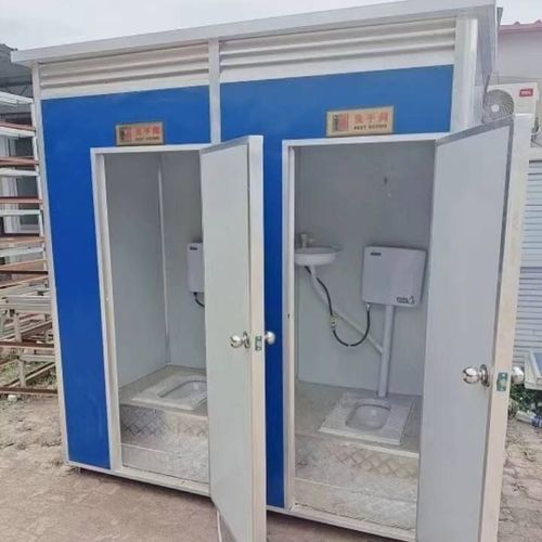
Mobile Toilet Circuit Diagram Image Translation
Currently, it is not possible to directly provide images of mobile toilet circuit diagrams, but some working principles of circuits related to mobile toilets can be introduced for reference.

Public Toilet Automatic Flushing Controller Circuit
The core function of the public toilet automatic flushing controller circuit is to flush the toilet by opening the solenoid valve at regular intervals. It can automatically adjust the flushing frequency according to different times of the day and night, with more flushing times during the day and longer intervals between flushes at night. Additionally, the circuit has a manual flushing control function to meet usage needs in special circumstances. In terms of power supply, the transformer T, VD1 - VD4, VD5, and C1 together form a 12V power supply circuit. Among them, the transformer T reduces the input AC voltage to an appropriate level; VD1 - VD4 form a rectifier bridge to convert AC power to DC power; VD5 acts as a voltage regulator to ensure the stability of the output voltage; and C1 is a filter capacitor used to smooth the DC voltage and reduce voltage fluctuations. The NE555 timer circuit is the core component of the entire control circuit. Together with the surrounding components, it forms a pulse signal oscillator with an automatically adjustable duty cycle. The pulse signals generated by this oscillator control the on-off state of the solenoid valve, thereby achieving the function of timed flushing.
Mobile Public Toilet Controller Circuit in Expressway Service Areas
After the controller of the mobile public toilet in an expressway service area is connected to a 220V power supply, it first converts the AC power to DC power through an AC-DC module, usually to 12V or 24V, to meet the power supply requirements of different devices. The converted DC power supplies devices such as the occupancy indicator, ceiling speaker, exhaust fan, toilet cubicle human body sensor, lighting, and smart door lock for the partition door. These devices are connected to the controller through IO signals. The controller can determine whether a toilet cubicle is occupied based on signals from the human body sensor, thereby controlling the on-off state of devices such as the lighting and exhaust fan. At the same time, it can also control the occupancy indicator and the smart door lock for the partition door to display the usage status of the toilet cubicle and automatically control the door lock, enabling centralized control and management and improving the usage efficiency and management level of the public toilet.