
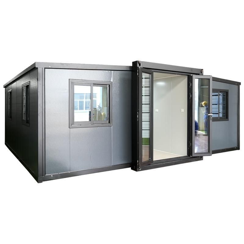
Container House Model Concept Diagram
Currently, there is no directly available concept diagram for container house models, but a design inspiration framework can be constructed based on actual cases and design ideas. The core of container house model design lies in modular combination and spatial reconfiguration, and its concept diagram should reflect structural logic, functional zoning, and aesthetic expression. The following elaborates on this from three aspects: design principles, typical cases, and drawing points.
I. Design Principles: Modularity and Spatial Reconfiguration
The essence of container houses is the "personalized reorganization of standardized modules". A single container is a standard cuboid (usually 6m×2.4m×2.6m), and during design, operations such as cutting, welding, and breaking through the container walls are required to break through the original spatial limitations. For example, horizontal cutting can extend the indoor depth, while vertical cutting can create high-ceilinged spaces; breaking through the side walls of adjacent containers can form connected areas suitable for public spaces such as living rooms and open kitchens; retaining part of the container structure as a partition can divide private areas such as bedrooms and bathrooms. The flexibility of modular combination is the core of the concept diagram, and it is necessary to show the splicing methods of containers (such as side by side, stacking, or offsetting) and connection nodes (welding points, bolt fixing positions) through line annotations.
II. Typical Case References
- Distill Studio Office Building in the United States: Composed of 32 containers, it adopts a colorful and lively appearance design. The concept diagram can highlight the arrangement logic of the containers (such as layered and offset stacking) and the color matching scheme (such as high-saturation color block contrasts like bright yellow, sky blue, and orange-red), while also annotating the distribution of public areas (such as conference rooms and lounge areas) and independent office spaces.
- ENS_projects' "Periscope Project": Defined outdoor courtyards and second-floor platforms through the linear and parallel arrangement of five intermodal containers. The concept diagram needs to reflect the axis relationship of the containers (such as parallel arrangement along the long side of the site), the elevation changes of the courtyards and platforms (such as sunken courtyards or elevated viewing platforms), and the interaction between the containers and the surrounding environment (such as introducing natural light through windows and setting up terraces to connect with the outdoor landscape).
III. Key Points for Drawing Concept Diagrams
- Structural Expression: Outline the container contours with bold solid lines, and annotate the dimensions and splicing methods; use dashed lines to indicate cutting parts and arrows to indicate the direction of spatial extension.
- Functional Zoning: Distinguish public areas (such as light gray), private areas (such as dark gray), and traffic flow lines (such as arrows indicating movement paths) through different fill colors or patterns.
- Aesthetic Details: Annotate the exterior wall materials (such as anti-corrosion wood, metal panels), window opening forms (such as floor-to-ceiling windows, skylights), and color schemes to reflect the design style (such as industrial style, minimalist style, or pastoral style).
If a specific concept diagram is required, it can be combined with the above principles to draw a three-dimensional model using software such as SketchUp and AutoCAD, or quickly express design ideas through hand-drawn sketches, with a focus on highlighting the combination logic and spatial innovation of the containers.



