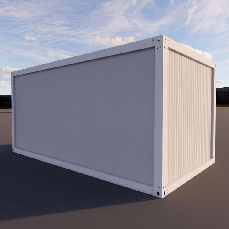
Container House 3Dmax Drawing Process
The drawing process of container houses in 3Dmax can refer to the conventional house modeling steps and be adjusted according to the characteristics of container houses. The details are as follows:

1. Preliminary Preparation and Model Planning
First, clarify the design requirements of the container house, including dimensions (standard containers are 20 feet or 40 feet, with typical lengths, widths, and heights of 6.06m×2.44m×2.59m or 12.19m×2.44m×2.59m), number of floors, and structural layout (such as whether they are stacked or spliced). After creating a new scene in 3Dmax, it is recommended to enable the 'Angle Snap' and 'Percentage Snap' tools to ensure modeling accuracy. You can start by drawing a cuboid as the basic module of the container, with dimensions consistent with the actual container, and then combine it into an overall structure through operations such as copying, rotating, and aligning.
2. Basic Structure Modeling
- Container Body: Use the 'Cuboid' tool to create a single container module, and adjust vertices, edges, or faces using the 'Edit Poly' modifier to simulate the corrugated steel plate texture of the container (which can be achieved through the 'Turbosmooth' or 'Displace' modifier). If rust or wear effects need to be represented, a 'Noise' map can be added in the material editor.
- Splicing and Connection: After copying the basic module, adjust its position using the 'Move' and 'Rotate' tools, and use the 'Align' tool to ensure seamless connection between modules. If designing a multi-story structure, 'connection' components (such as stairs and platforms) need to be added. These can be drawn as outlines using 'Splines' and then converted into editable polygons, or directly created using the stair tool in the 'AEC Extended' section.
3. Detail Optimization and Opening Design
- Door and Window Openings: Select the corresponding face on the container wall, enter the 'Edge' level, use the 'Connect' tool to divide the area, and then delete the excess faces to form door and window openings. The edges of the openings can be modified with the 'Bevel' modifier to simulate cutting marks.
- Additional Structures: If canopies, sunshades, etc., need to be added, draw their outlines using 'Splines' and then 'Extrude' them into three-dimensional models, or use 'Boolean' operations to cut grooves from the main body.
4. Material and Rendering Settings
- Material Assignment: Metal materials are usually used for the surface of containers. Adjust the 'Diffuse' color (such as iron gray), 'Reflection' intensity (about 50-70%), and 'Specular Level' (0.8-0.9) in the material editor. Corrugated textures can be added through the 'Bump' channel using 'Noise' or 'Bitmap' maps.
- Environment and Lighting: Add 'VRay Light' or 'Target Directional Light' to simulate natural light, adjusting intensity and shadow types; the background can be set to an HDR map or a solid color to enhance scene realism.
- Rendering Output: Use the 'VRay Renderer' or the default scanline renderer, set the resolution (such as 1920×1080) and anti-aliasing parameters, and finally generate high-definition images or animations.
5. Post-Adjustment and Inspection
Check the model proportions, splicing gaps, and material details to ensure there are no issues such as model penetration or deformation. You can check each part individually using the 'Isolate Selection' function or use the 'Measure' tool to verify dimensional accuracy.