
Assembly Drawing of Concrete Prefabricated House
Currently, it is not possible to directly provide the assembly drawing of concrete prefabricated houses. However, the component composition and connection methods can be explained in conjunction with the technical characteristics of the assembled monolithic composite concrete structural system, and it is recommended to obtain specific diagrams through standard drawing collections.
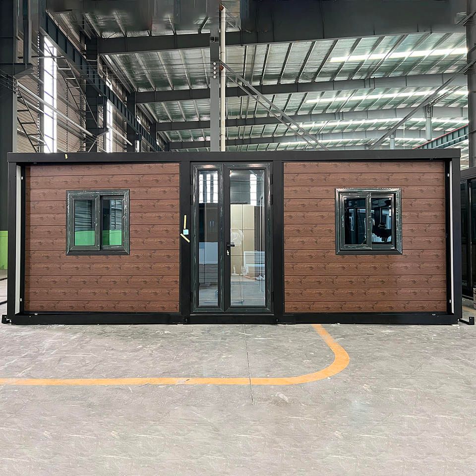
The assembled monolithic composite concrete structural system is one of the typical technical paths for concrete prefabricated houses. Its core lies in achieving collaborative work between prefabricated components and cast-in-place parts through the "cavity + lap + post-cast" process. The main components of this system include three categories:
- Composite interior wall panels: Composed of two layers of prefabricated concrete panels and built-in formed steel reinforcement skeletons. The prefabricated panels provide initial stiffness, and the steel reinforcement skeletons ensure the anchoring performance with the post-cast concrete, ultimately forming an overall load-bearing wall.
- Sandwich composite exterior wall panels: Adopt a multi-layer composite structure. The outer layer is a prefabricated concrete facing panel (responsible for decoration and protection), the middle layer is an insulation board (to achieve thermal performance), and the inner layer is the wall inner shell (connected to the indoor structure). The sandwich structure fixes each layer with connectors to prevent interlayer slippage.
- Composite columns: Adopt a formwork form. The outer layer is a prefabricated concrete formwork (replacing traditional formwork), with a built-in formed steel reinforcement skeleton inside. During construction, after positioning the formwork, core area concrete is poured to form an overall column.
The connection nodes of components are crucial for ensuring structural safety. This system adopts the following typical connection methods:
- Vertical connection of shear walls: The steel reinforcements of the upper and lower shear walls are connected by lapping. The lap length must meet the design code requirements, and post-cast concrete fills the cavity to achieve force transfer.
- Horizontal connection nodes: Include forms such as straight, L-shaped, and T-shaped. Adjacent walls are spliced through reserved steel reinforcements or connectors, and the post-cast strip concrete wraps the nodes to form overall load-bearing nodes.
- Beam-column connections: The main reinforcements are connected mechanically using steel reinforcement sleeves (such as grouting sleeves) or indirectly by lapping (such as inserting reserved steel reinforcements into the column and then pouring concrete), ensuring that the bending moment and shear force at the beam end are effectively transferred to the column.
If specific assembly drawings are required, it is recommended to refer to the following standards:
- Technical Specification for Assembled Monolithic Composite Concrete Structures (DBJ61/T 183): Contains detailed diagrams of component splitting, node construction, and construction processes.
- Technical Specification for Prefabricated Concrete Structures (T/CECS 579): Provides a general assembly drawing collection covering the connection node designs of various structural systems. Through standard drawing collections, key information such as component dimensions, steel reinforcement layouts, and post-cast areas can be obtained intuitively, providing a basis for design and construction.



