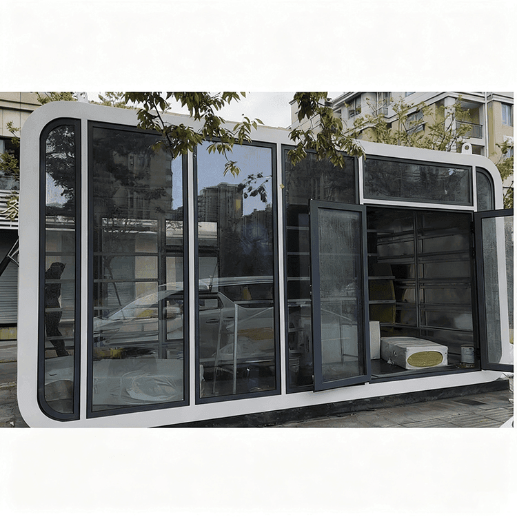
Prefabricated Wall Structure Diagram of House
The prefabricated wall structure diagram of a house mainly involves two aspects: the distinction between load-bearing and non-load-bearing walls, and the display of prefabricated components in prefabricated buildings.

Prefabricated Wall Structure Diagram Related to the Distinction Between Load-Bearing and Non-Load-Bearing Walls
In floor plan drawings, for prefabricated wall structures, different lines are usually used to distinguish between load-bearing and non-load-bearing walls. Walls marked with thick black lines are generally load-bearing walls. These walls have prefabricated slabs placed on them, bear the main weight of the house, and play a crucial supporting role in the house structure. They must not be removed at will, as doing so would seriously affect the structural safety of the house. Walls marked with gray or white lines are non-load-bearing walls. They bear relatively less weight and have a minor impact on the overall structure of the house. Under compliance with relevant regulations and safety requirements, they can be modified to a certain extent. In the structural drawings of brick-and-concrete houses, black thick lines also represent load-bearing walls, while gray lines represent non-load-bearing walls. In 3D schematic diagrams, red walls are non-load-bearing walls, which can be removed or otherwise operated on according to actual needs.
Prefabricated Wall Structure Diagram Related to the Display of Prefabricated Components in Prefabricated Buildings
In prefabricated buildings, the prefabricated wall structure diagram has a unique way of presentation. Green text usually represents commonly used prefabricated exterior wall components, etc. These components are widely used in prefabricated buildings and can meet the functional and aesthetic requirements of building exterior walls. Red text represents less commonly used components such as prefabricated load-bearing walls, prefabricated columns, and prefabricated beams, which involve structural stability issues. The same prefabricated component can be divided into two types: simplified components and detailed components. Simplified components are mainly used in project models for conventional plan and elevation drawings, enabling a quick display of the overall layout and appearance of the building. Detailed components are used for detailed design drawings and modeling, etc. They are placed in a separate project model for detailed drawing design. Simplified and detailed components are identical in three-dimensional dimensions, but detailed components include more detailed components such as bolt sleeves, air-conditioner reserved holes, and galvanized steel plates. Through the reasonable use of detailed and simplified components, detailed drawings of prefabricated exterior wall components can be produced, such as elevation details, section details, and embedded part location diagrams, providing detailed and accurate guidance for the construction of prefabricated walls in prefabricated buildings.