Design Drawings for Houses Built with Prefabricated Slabs
There is a relatively complete system of design drawings for houses built with prefabricated slabs. Taking a five-story prefabricated slab building as an example, it includes various key drawings.
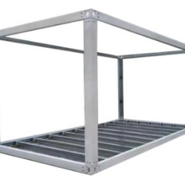
Basement Structure Drawing: This drawing mainly displays the overall layout and structural configuration of the basement. It clearly marks the positions and thicknesses of the basement walls. When prefabricated slabs are used, it details the laying methods, specifications, and connection node practices of the prefabricated slabs on the basement ceiling and other parts. Additionally, for the basement columns, it provides their dimensions and reinforcement details to ensure that the basement structure can withstand the upper loads as well as the effects of underground soil and water pressure, guaranteeing structural safety and stability.
First-Floor Plan and Structure Drawing: It presents the spatial layout and structural information of the first floor. It clearly divides the locations of various functional areas such as the living room, bedrooms, kitchen, and bathroom. In terms of structure, it marks the wall materials (with special instructions if prefabricated slab-related walls are used), the positions and dimensions of door and window openings. For the first-floor ground, if prefabricated slabs are laid, it explains the arrangement pattern of the slabs, slab joint treatment, and other details to ensure ground flatness and structural integrity.
Ring Beam Layout Drawings for Each Floor: Ring beams are important components that enhance the overall rigidity and stability of the house. This drawing indicates the positions, cross-sectional dimensions, and reinforcement details of the ring beams on each floor. Ring beams are generally arranged along the walls and are reasonably set on different floors according to structural load requirements. Through reliable connections with the walls and columns, they form an overall framework, effectively resisting the effects of uneven settlement and horizontal loads (such as wind loads and seismic actions) on the house.
Plan and Structure Drawings for the Second to Fourth Floors: Similar to the first-floor plan and structure drawing, these mainly display the spatial and structural layouts of each floor. However, adjustments are made in the settings of walls and doors and windows according to the functional requirements and usage characteristics of different floors. Meanwhile, for floors where prefabricated slabs are used for the floor surface, it details key parameters such as the selection, laying direction, and support length of the prefabricated slabs to ensure that the floor can safely bear the upper loads.
Stair Section Reinforcement Drawings and Entrance Stair Section Reinforcement Drawings: These two types of drawings focus on the structural design of the stairs. They provide geometric information such as the sectional shape of the stairs, step dimensions, and platform heights. In terms of reinforcement, they detail the reinforcement arrangements of the stair beams, stair slabs, and tread slabs, including the diameters, spacings, and anchorage lengths of the reinforcing bars, ensuring that the stairs have sufficient strength and rigidity under loads such as personnel passage.
Roof Structure Drawing: The roof structure drawing shows the construction layers and structural forms of the roof. It explains the types and laying methods of the prefabricated slabs used for the roof, as well as the roof's insulation and waterproofing practices. Meanwhile, for the roof support structures such as roof trusses and purlins, it provides their dimensions, spacings, and connection methods to ensure that the roof can withstand loads such as wind and snow, guaranteeing the house's waterproofing and insulation performance.
You may also like
Portable Toilet Eco-Friendly: MOQ, Samples & Quotation Guide
Read More
Top Portable Toilet Color Steel Manufacturers: How to Choose a Factory Partner
Read MorePortable Toilet Picture: Types, Features & Buying Tips
Read More