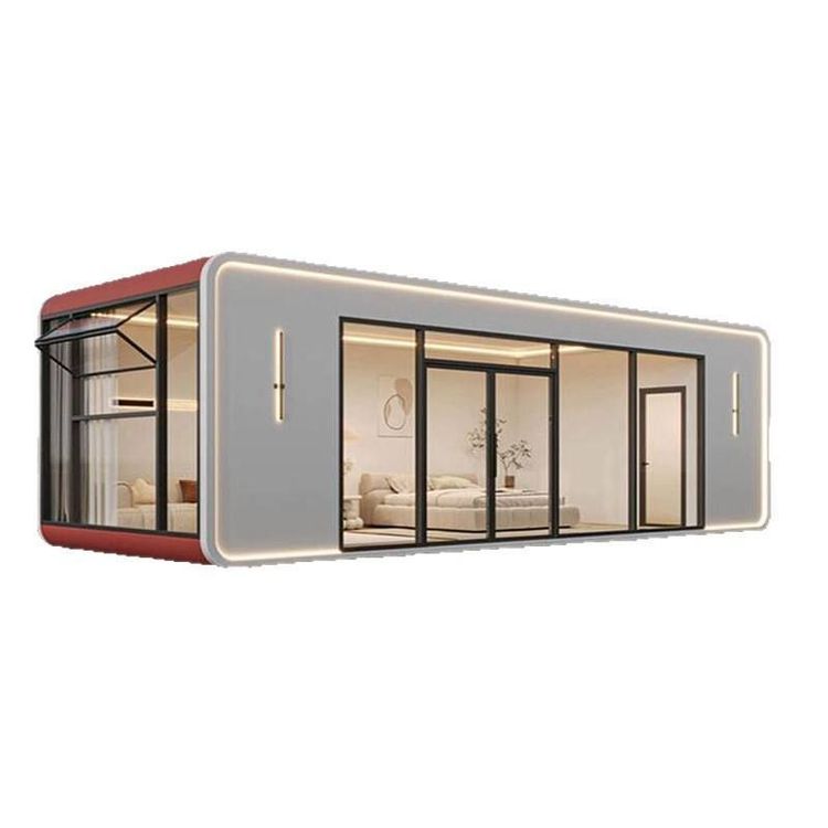
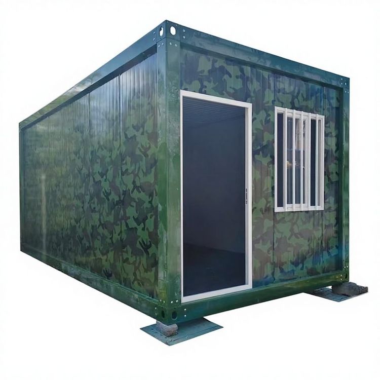
Custom Drawings for Prefabricated Houses
Custom drawings for prefabricated houses need to comprehensively consider plot characteristics, lifestyle adaptability, and detailed design, while leveraging BIM technology to enhance design accuracy and efficiency.

I. Design Principles: Aligning with Plot Characteristics and Lifestyle Needs
Custom drawings for prefabricated houses should be based on plot features to optimize spatial layouts. For example, in a villa project with a total plot area of 293.74 square meters, oriented south to north with the main entrance facing north and adjacent to the street, the design breaks through traditional lighting limitations by incorporating 'windows on all sides' to improve indoor transparency. In terms of functional zoning, the ground floor adopts a separation of dynamic and static areas: a double-car garage and exclusive porch are located on the north side facing the street, adjacent to guest rooms and a public restroom; the east side integrates the kitchen, laundry room, and staff quarters, forming an independent functional area with a separate entrance; the south-facing core area plans the living room and dining room to create a public activity center. The second and third floors focus on privacy and experience: the second floor features an open terrace above the north porch, a master bedroom with a viewing balcony above the garage, a walk-in closet and an independent master bathroom above the staff quarters, and two guest bedrooms and a landscape living room in the southeast corner; the third floor transforms the master bedroom area into an extra-large terrace to meet diverse needs.
II. Detailed Design: Balancing Practicality and Safety
Drawings should be detailed down to structural nodes to address practical usage issues. For example, the finished surface of the terrace is 0.10 meters lower than the indoor level, and the balcony finished surface is 0.05 meters lower than the indoor level, preventing stormwater backflow through elevation differences; the positioning diagram for embedded parts must accurately mark component connection points to ensure construction accuracy; detailed components should include fine structural elements such as door and window openings and insulation layers to avoid later modifications.
III. Technological Advancement: The Application of BIM Forward Design
Traditional CAD drafting is gradually being replaced by BIM technology, enabling automated output from 3D modeling to 2D drawings. BIM design works collaboratively through 'simplified components' and 'detailed components': simplified components are used for project modeling and conventional drawing outputs (such as plans and elevations), while detailed components contain more fine-grained information (such as embedded parts and node structures) for detailed design drawing outputs and modeling. For example, prefabricated exterior wall components can generate elevation details, section details, embedded part positioning diagrams, and vertical numbering diagrams through BIM, enhancing the completeness and constructability of the drawings.
Custom drawings for prefabricated houses need to balance personalized needs with standardized production, achieving full-process optimization from concept to implementation through scientific design principles, refined node handling, and BIM technology empowerment.