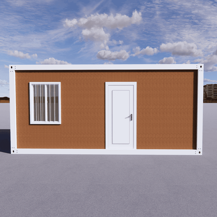
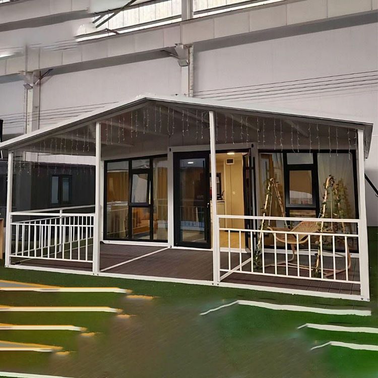
Outdoor Prefabricated House Structural Diagram
Currently, there is no complete structural diagram directly targeting outdoor prefabricated houses, but the production and drawing methods of prefabricated exterior wall components in prefabricated buildings can be referenced to understand the generation logic of relevant diagrams.
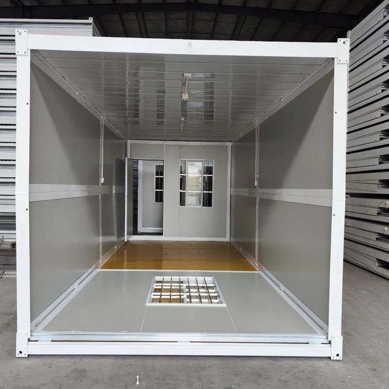
In the field of prefabricated buildings, the drawing of prefabricated component diagrams is a crucial step in project advancement, and the structural design of outdoor prefabricated houses can also draw on similar ideas. Taking prefabricated exterior wall components as an example, their diagram drawing is divided into two directions: simplified components and detailed components.
Drawing methods for simplified components: Simplified components are mainly used for regular displays in project models, such as floor plans and elevation views. When drawing these diagrams, the focus is on highlighting the overall outline and basic dimensions of the components to meet the needs of initial project planning and scheme comparison. For example, in a floor plan, the length, width, and positional relationship with surrounding structures of the prefabricated exterior wall components are marked; in an elevation view, information such as their height and appearance are displayed. This drawing method is concise and clear, enabling the rapid transmission of basic component information and providing a basis for the overall layout and preliminary design of the project.
Drawing methods for detailed components: Detailed components are used for detailed design and modeling and contain more detailed information. The diagram drawing of detailed components is more precise, covering the positions, dimensions, and connection methods of detailed components such as bolt sleeves, air-conditioning reserved holes, and galvanized steel plates. By drawing diagrams of detailed components, elevation details, section details, and embedded part location diagrams of the components can be generated. The elevation details will show in detail the textures and decorative lines on the surface of the components; the section details reveal the internal structural layers and construction methods of the components; the embedded part location diagrams precisely mark the positions and specifications of the embedded parts to ensure accurate installation during construction.
The drawing of structural diagrams for outdoor prefabricated houses can also refer to the above methods. First, determine the overall layout and basic dimensions of the house, and draw simplified diagrams for initial planning and display; then, conduct detailed design on key parts and detailed structures, and draw detailed diagrams to provide precise guidance for construction.