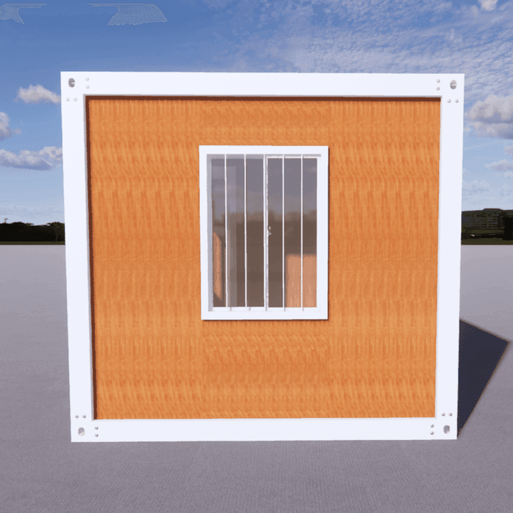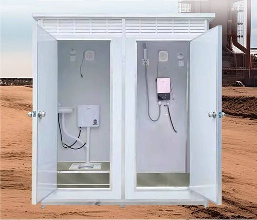
Mobile Toilet Water and Electricity Connection Diagram
Currently, there is no directly publicly available diagram for the water and electricity connection of mobile toilets, but the basic logic and key aspects of the water and electricity connection can be inferred based on their power supply architecture and facility configurations.
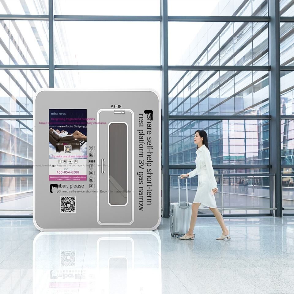
The water and electricity connection of mobile toilets needs to balance functional realization and safety regulations, with the core being the rational distribution of external water and electricity resources to internal equipment. From the perspective of power supply, the typical power supply architecture of mobile public toilets in highway service areas is as follows: After the controller is connected to a 220V AC power source, it is converted into 12V or 24V DC power through an AC-DC module to supply power to equipment such as occupancy indicator signs, ceiling speakers, exhaust fans, toilet stall human body sensors, lighting fixtures, and smart locks for partition doors. These devices are connected to the controller via IO signals, enabling centralized control and status feedback. For example, the start and stop of lighting fixtures and exhaust fans can be triggered by human body sensors, and the controller adjusts the output voltage according to the signals to ensure that the equipment operates as needed.
The key aspects of water and electricity connection include:
- Power source access and conversion: The external 220V power source needs to be introduced into the mobile toilet through a waterproof junction box and connected to the input terminal of the controller. The AC-DC module should have overload and short-circuit protection functions to prevent equipment damage due to voltage fluctuations. The converted DC power is distributed to each device through a distributor, which should be labeled with the voltage level to avoid misconnection.
- Equipment power supply circuits: Lighting fixtures, exhaust fans, and other equipment need to be connected to the output terminal of the controller via independent circuits, and the circuit specifications should be selected according to the power of the equipment. For example, if a lighting fixture has a power of 10W and is powered by 12V, the circuit current is approximately 0.83A, and a 1.5mm² copper wire can be selected. When the power of the exhaust fan is higher, the wire diameter should be increased accordingly.
- Water and electricity isolation design: To avoid the risk of electric leakage, the power supply circuits should maintain a safe distance from water pipes, flush tanks, and other water facilities, or be wrapped with waterproof sleeves. Water connections should use PPR pipes or galvanized steel pipes, and the joints should be sealed to prevent leakage.
It should be noted that the water and electricity connection of mobile toilets should be carried out by professional electricians and comply with local electrical safety regulations. During actual installation, the wiring diagram in the equipment manual can be referred to, and the layout can be carried out in combination with the positions of on-site water and electricity interfaces to ensure reliable connection and convenient maintenance.