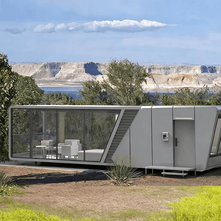
Mobile Toilet Installation Construction Drawing
The mobile toilet installation construction drawing is a core document guiding on-site operations, requiring detailed design of structural, water supply and drainage, electrical, and other systems to ensure functionality and safety.

1. Overall Layout Design
The construction drawing should determine the layout form based on the site terrain, pedestrian traffic, and surrounding environment, with common types including single-unit, multi-unit combination, and barrier-free dedicated styles. The floor plan should clearly mark the location of each toilet cubicle, aisle width (usually ≥90cm), entrance and exit directions, and overall dimensions (length, width, height) to ensure transportation and installation meet standards. Ventilation design should include vents at the top or windows on the side walls, while lighting can be supplemented by natural light windows or artificial lighting to avoid a dark and damp interior.
2. Structural System Details
The frame uses lightweight metal materials (such as aluminum alloy or galvanized steel pipe), and the drawing should indicate the connection method between columns and beams (welding or bolt fixation) and the location of key nodes. The walls should distinguish between inner and outer layer materials: the outer layer commonly uses waterproof panels (such as PVC panels or metal panels), while the inner layer can add insulation (such as polystyrene foam), with thickness and installation sequence specified. The roof design should include a slope (usually 3%-5%), gutter location, and rainproof measures (such as waterproof membranes or metal tiles), with sectional drawings showing the connection details between the roof and walls to ensure a stable and leak-proof structure.
3. Water Supply and Drainage System Planning
The water supply section should depict the direction of water pipes, valve locations, and water tank installation points, specifying pipe material specifications (such as PPR pipes or galvanized steel pipes) and connection methods (hoses or hot-melt connections), with antifreeze measures like electric tracing tape added in cold regions. The drainage system includes toilet waste pipes, septic tank or collection tank layout, with arrows indicating water flow direction, pipe slope (≥2%), and capacity marked to prevent blockages. The installation location of water-saving devices (such as low-flow flush valves) should be specified separately to ensure water efficiency meets standards.
4. Electrical System Design
The circuit wiring diagram should indicate power access points, switch and socket locations, with wire specifications chosen based on load (such as 2.5mm² copper wire for lighting and 4mm² copper wire for sockets), and waterproof cables (IP65 or higher protection level) used. The lighting section should specify the type of fixtures (such as LED explosion-proof lights) and installation height (usually 2.2-2.5m), with emergency lighting devices (such as safety exit signs) powered by an independent circuit. The circuits for exhaust fans or heaters should be drawn separately to ensure electrical safety.
5. Interior Facilities and Decoration
The fixed positions of toilets, sinks, mirrors, and other components should be precisely marked, with enlarged drawings showing the details of sink pipe connections and support structures. The decoration section should specify wall (anti-slip tiles or composite panels) and floor materials (anti-slip tiles or epoxy resin), with color choices coordinated with the overall environment. The locations of auxiliary facilities (such as hooks, paper towel holders, trash cans) should optimize space utilization, with barrier-free toilet cubicles requiring additional handrails and alarm devices.
6. Environmental Protection and Safety Features
The drawing can include the installation location of solar panels (for power supply) and battery storage unit layout, with rainwater collection devices designed on the roof or side walls (for flushing or cleaning). In terms of safety, fire-resistant material applications (such as rock wool filling in walls) should be marked, and the electrical system should be equipped with leakage protection devices to ensure safe use.