Mobile Toilet Drawing Instruction
For mobile toilet drawing instruction, you can refer to the following steps and resources and carry out operations in combination with design requirements and specifications:

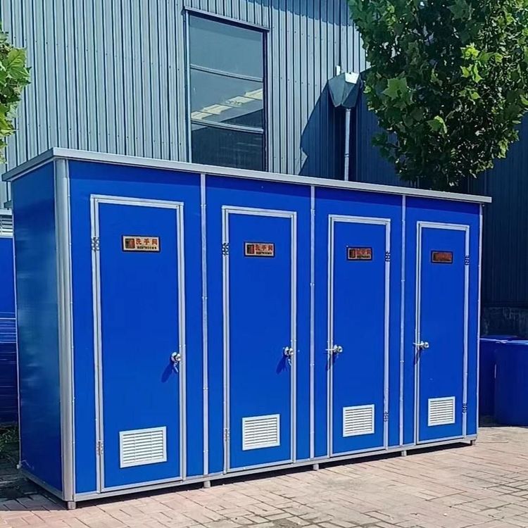
1. Clarify Design Requirements and Types First, determine the functional positioning of the mobile toilet, such as whether it includes barrier-free facilities, the number of squatting positions (e.g., a two-squatting-position design), and whether a sink is needed. For customized designs, you can refer to the hand-drawn cases of Dezhou Hongtu Metal Products Co., Ltd. It offers VIP customization services for apple-shaped toilets, covering the layout of public sinks. Specific dimensions and style requirements can be clarified through one-on-one communication. Such cases are suitable for scenarios requiring personalized appearances or special functional combinations.
2. Refer to Structural Drawings and Drawing Techniques For structural design, you can download the SolidWorks2016 drawing of a two-squatting-position mobile toilet provided by Mfeng.com. This resource includes isometric views, front views, left views, and perspective views, which can clearly display the three-dimensional structure and planar layout of the toilet. When drawing, pay special attention to the following aspects:
- Dimension Marking: Ensure that the door width, distance between squatting positions, aisle width, etc., comply with ergonomics (e.g., door width ≥ 900mm).
- Component Connection: Clarify the assembly methods of components such as walls, roofs, and sewage pipes.
- Perspective Drawing: Use perspective relationships to express spatial hierarchy and assist in design reviews. If using other drawing software (e.g., AutoCAD), you can refer to the proportions and structural logic in the SolidWorks drawing for conversion.
3. Follow Barrier-Free Design Specifications (if applicable) If the mobile toilet needs to meet barrier-free usage requirements, strictly refer to the Unified Standard for Civil Building Design:
- Toilet Area: Continuous handrails should be installed on both sides, with a height of 700-850mm from the ground.
- Call Device: A distress call button should be installed next to the toilet, with an installation height of 400-500mm from the ground.
- Clothes Hook: The height of the low-position clothes hook from the ground should be ≤ 1200mm.
- Aisle Width: The clear width of the barrier-free aisle should be ≥ 900mm, and the clear width after the door leaf is opened should be ≥ 800mm. These details should be clearly marked in the drawing, and different line types (e.g., dashed lines to indicate the range of handrails) should be used to enhance readability.
4. Optimize Details and Markings After completing the basic structure, supplement the following content:
- Material Description: Mark the materials of the walls, roof, and floor (e.g., color steel plates, non-slip floor tiles).
- Sewage Disposal Method: Indicate whether it is a direct-discharge or fecal-storage type, and mark the position of the sewage outlet.
- Ventilation Design: If natural ventilation is used, mark the position of the ventilation openings; if mechanical ventilation is used, mark the model of the fan and the pipe diameter.
- Dimension Tolerance: Mark the machining tolerance for key components (e.g., door frames, squatting-position partitions) to ensure assembly accuracy.
5. Verification and Adjustment After drawing is completed, verify the design rationality from the usage scenario:
- Space Utilization: Check whether the layout of squatting positions, sinks, and aisles is compact and free of conflicts.
- Human Activity Range: Simulate users' actions such as opening and closing doors, using the toilet, and washing hands to confirm there is no sense of confinement.
- Specification Compliance: Compare with barrier-free standards or mobile toilet industry standards to ensure all parameters meet the requirements. Adjust the drawing according to the verification results to finally form a deliverable construction drawing or 3D model.