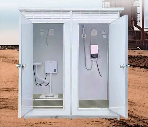
Mobile Toilet Circuit Diagram
Currently, there is no complete circuit diagram directly targeting mobile toilets, but reference solutions can be provided based on circuit designs for automatic flush controllers in public toilets and infrared-sensing faucets, with specific adjustments needed according to equipment models and installation environments.

The circuit design for mobile toilets should focus on core functions, including automatic flushing, sensor-based water supply, power adaptation, and environmental adaptability adjustments. The following are key design points:
1. Reference for Automatic Flush Control Circuit
The circuit for automatic flush controllers in public toilets uses the NE555 timer circuit as its core, achieving day-night mode switching through a photoresistor: short flushing intervals during the day (e.g., every 10 minutes) and long intervals at night (e.g., every 1 hour). The circuit includes transformer voltage reduction, rectification and filtering, NE555 oscillation module, and solenoid valve drive components. The photoresistor and voltage-dividing resistor form a light-controlled circuit, triggering high-frequency oscillation during the day when the resistance is low and low-frequency oscillation at night when the resistance is high, thereby controlling the on-off time of the solenoid valve. This design can be directly applied to the flushing systems of urinals or squat toilets in mobile toilets, with adjustments to the NE555's RC timing parameters based on the water tank capacity.
2. Reference for Sensor-Based Water Supply Circuit
The circuit for infrared-sensing faucets emits signals through a 40kHz infrared oscillator, with the photodetector receiving reflected waves. The KA2184 dedicated chip processes the signals and drives a solid-state relay to control the solenoid valve. The power supply section uses transformer voltage reduction + rectifier bridge + voltage regulator chip (e.g., 7805) to provide stable DC power. The sink in mobile toilets can adopt this circuit, with attention to:
- Aligning the infrared emitter and receiver for installation to avoid interference from direct sunlight;
- Selecting a solid-state relay with a voltage rating of 220V and a switching current of ≥1A to match the solenoid valve;
- Adjusting the sensing distance by regulating the potentiometer or changing the power of the infrared emitter.
3. Key Points for Power Supply and Circuit Design
If the mobile toilet uses 220V mains power, power lines should be pre-buried, and a leakage protection switch should be installed. Sensors, solenoid valves, and other equipment should be grounded through three-prong sockets. If low-voltage DC power (e.g., 12V/24V) is used, a switching power supply module should be configured, and lightning protection should be added. The water supply and drainage system should be planned in advance:
- The positions of the water inlet and outlet for urinals should match the dimensions of the sensor connection pipes (usually DN15 or DN20);
- Circuit wiring should be kept at least 30cm away from water pipes to avoid short circuits caused by a humid environment;
- Outdoor mobile toilets should be equipped with waterproof junction boxes, and all connections should be insulated.
4. Environmental Adaptability Optimization
In cold northern regions, heating films should be installed on circuit boards to prevent parameter drift in capacitors and resistors due to low temperatures; in humid southern regions, desiccants should be placed in control boxes, and moisture-resistant electronic components should be selected. All circuit designs should pass EMC testing to ensure compliance with standards for electromagnetic interference resistance.