Mobile Toilet Circuit Connection
The circuit connection of mobile toilets requires different solutions based on various types and requirements, as detailed below:
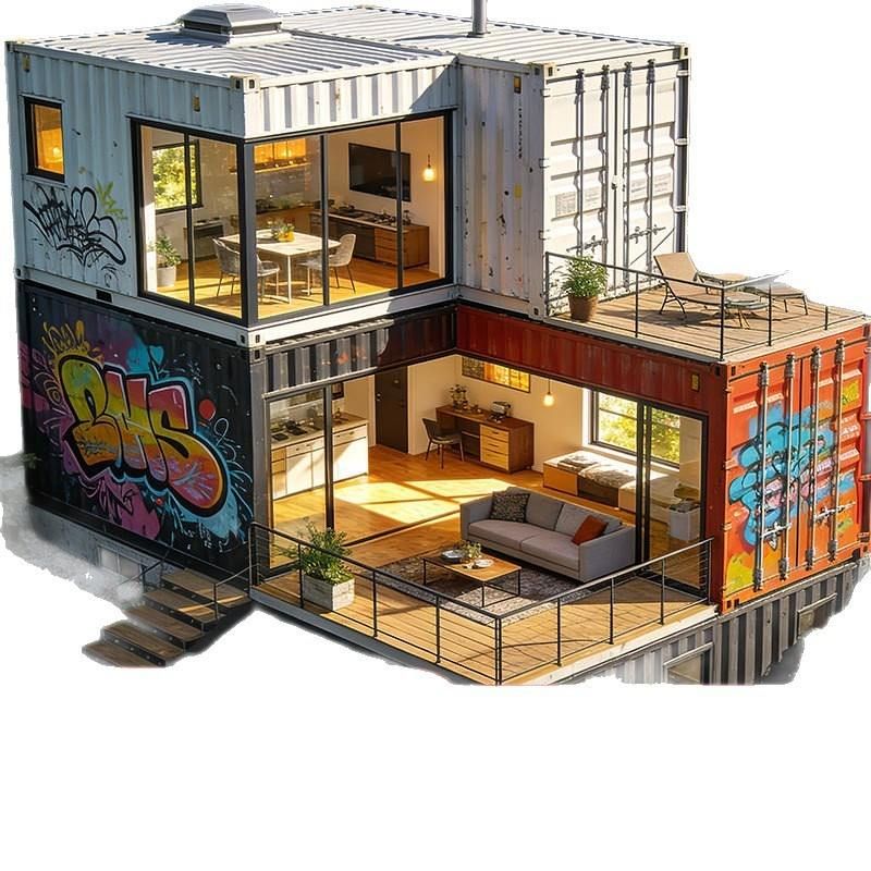
Mobile Toilets in Expressway Service Areas
After the controller is connected to a 220V power supply, an AC-DC module converts the alternating current into direct current (usually 12V or 24V) to power devices such as occupancy/vacancy signs, ceiling speakers, exhaust fans, toilet-stall human presence sensors, lighting fixtures, and smart locks for partition doors. Devices are connected to the controller via IO signals for centralized control and management. For example, when a human presence sensor detects someone entering a toilet stall, it sends a signal to the controller via an IO signal, and the controller then activates lighting fixtures, exhaust fans, and other devices; when no one is present, the devices are turned off to save energy.
Modular Mobile Toilets
The power supply system is connected using a 380V three-phase five-wire system, with a designed load level of Class III and a total calculated load of 12kW.
- Device Configuration and Connection: Energy-efficient LED fixtures (10W/AC220V) are installed at the center of the ceiling or above toilet stalls; sensor-activated faucets (DC12V/0.5A) are installed beneath sinks; electric tracing devices (220V/15W/m) are installed on the outer walls of water supply and drainage pipes; exhaust fans (220V/30W) are installed in ceiling corners; and emergency call devices (DC24V/0.1A) are installed on the side walls of accessible toilet stalls.
- Cable Laying: The power supply access point is a municipal distribution box located 15m from the toilet. Cables are laid along the edge of sidewalks and protected by φ100mm galvanized steel pipes (2m in length) when crossing roadways, with flared ends at both ends of the pipes. Cables are laid using a manual pulling method, with a 1.5m allowance reserved at intermediate joints, a bending radius of at least 12 times the cable diameter, and covered with 200mm-thick plain soil and compacted in layers after laying.
- Distribution Box Installation: The distribution box is fixed to the exterior wall of the toilet (1.5m above the ground) using M10 expansion bolts, and the box body is reliably connected to the grounding main line (6mm² copper wire) to ensure electrical safety.
Urinal Sensors
There are two common power supply methods: battery power and AC transformer power:
- AC Transformer Power: The power supply is connected using a male-female plug, with two exposed terminals for AC power connections. The power output consists of two sets of wires (one set for each male-female terminal). If an external battery is used for power, the AC power is not connected. After the power supply provides power to the sensor circuit, the sensor is connected via paired plug connectors (the red male-female wires are the power wires), and then the control power output from the sensor is connected to the solenoid valve.
- Push-Button Switch Control: If a push-button switch is used to control the sensor, simply insert the solenoid valve's wiring plug into the power output plug.