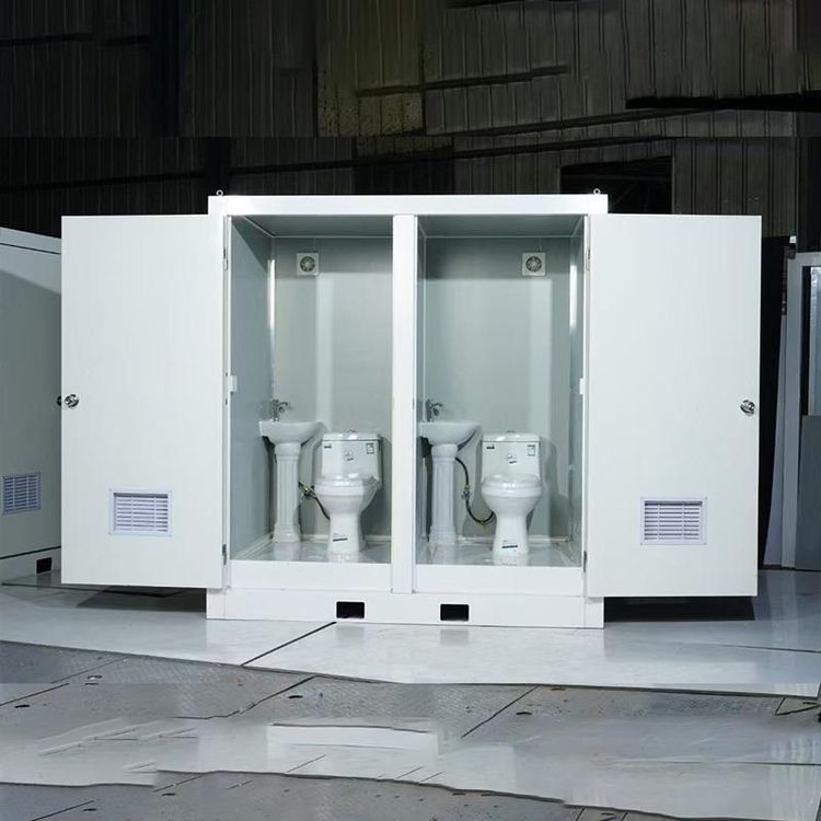
Mobile Toilet Circuit Board Diagram
Currently, there is no detailed diagrammatic information directly related to the circuit board diagram of mobile toilets, but circuit principles related to electronic toilet seat covers and automatic flushing controllers in public toilets can be provided for reference.

Circuit Principles Related to Electronic Toilet Seat Covers
The circuit control section of an electronic toilet seat cover works in conjunction with the water circuit, mechanism, and heater components. The water circuit section contains multiple key components whose normal operation relies on precise circuit control. For example, the solenoid valve is an important element in the water circuit. It controls the on/off of water flow through circuit control. When the circuit receives the corresponding command signal, the solenoid valve opens or closes, thereby controlling the entry of water into the instant-heating component or the flushing component. The ceramic heating tube, temperature control switch, temperature sensor, and water level switch in the instant-heating component are also closely connected to the circuit. The ceramic heating tube is responsible for heating the water. The temperature control switch and temperature sensor monitor the water temperature in real-time and feed the temperature information back to the circuit control system. The circuit adjusts the power of the heating tube according to the set temperature value to ensure that the water temperature remains stable within an appropriate range. The water level switch is used to monitor the water level inside the instant-heating component. When the water level is too low, the circuit will issue an alarm or take corresponding protective measures to prevent the heating tube from burning out due to dry operation.
Circuit Principles of Automatic Flushing Controllers in Public Toilets
The circuit of an automatic flushing controller in public toilets consists of a 12V power supply circuit formed by transformer T, VD1 - VD4, VD5, and C1. Transformer T converts the mains voltage to an appropriate voltage value. VD1 - VD4 form a rectifier bridge that converts alternating current to direct current. VD5 serves as a voltage stabilizer, and C1 is used for filtering to make the output 12V direct current more stable. The NE555 time-base circuit, together with surrounding components, forms a pulse signal oscillator with an automatically adjustable duty cycle, which is the core part of the entire automatic flushing controller. This oscillator can generate pulse signals with different duty cycles according to the set parameters. The pulse signals control the solenoid valve to flush the toilet at regular intervals. By adjusting the parameters of the resistors, capacitors, and other components around the NE555 time-base circuit, the frequency and duty cycle of the pulse signals can be changed, thus achieving different flushing times and intervals to meet the needs of different usage scenarios.