Mobile Prefab Toilet Assembly
The assembly of mobile prefab toilets mainly involves the combination of functional units, basic assembly steps, and system integration and maintenance, as detailed below:

I. Combination Logic of Functional Units
Mobile prefab toilets consist of three core functional units:
1. Waste Treatment Unit: This unit employs solid-liquid separation technology to treat excreta through physical or chemical means, reducing odors and pollution risks. For example, some designs use biodegradable materials to accelerate solid decomposition, while liquids are discharged into collection containers or purification systems through dedicated pipes.
2. Water Resource Management Unit: Responsible for water supply and drainage tasks. The water supply system may include storage tanks, water pumps, and water-saving fixtures (such as sensor-activated faucets). The drainage system is connected to the treatment unit or external sewage outlets through pipes. Some high-end models are equipped with water recycling devices to achieve repeated water utilization.
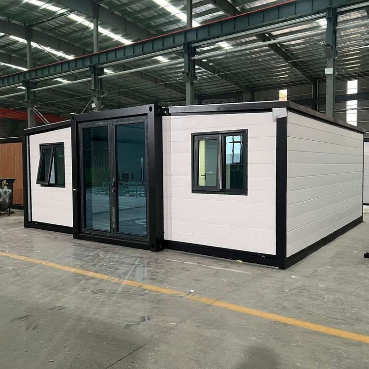
3. Spatial Structure Unit: Focuses on material selection and layout planning. The main frame is typically made of lightweight, high-strength materials (such as aluminum alloy or galvanized steel), while the walls and roof use fire-resistant and waterproof panels (such as color-coated steel plates or PVC panels). The layout should consider both ease of use and space utilization, with the positions of doors, windows, and ventilation openings conforming to ergonomic principles.
II. Basic Assembly Steps
1. Simple 'Building Block' Assembly:
Some mobile toilets do not require complex civil engineering work, and the assembly process is similar to building with blocks. First, the columns are fixed, and then the components are aligned and connected using clips or bolts to ensure structural stability. Such designs usually have pre-embedded connectors to reduce on-site processing and are suitable for rapid deployment scenarios.
2. Standardized Tool-Assisted Assembly:
Tools such as electric drills, 4.2mm drill bits, and rivet guns are required. The specific steps are as follows:
- Corner Installation: Fix the corner pieces at the corners of the frame according to the design drawings to serve as structural support points.
- Panel Assembly: Insert the wall and roof panels into the slots, align the edges, drill holes with a drill bit, insert rivets, and secure them with a rivet gun to ensure no gaps between the panels.
- Pipe and Electrical Connections: Connect the water supply and drainage pipes and electrical circuits according to the requirements of the functional units, paying attention to the tightness of the interfaces to prevent leakage or short circuits.
III. System Integration and Maintenance Points
1. System Integration:
The units are coordinated through pipes (such as sewage pipes and water supply pipes) and electrical controls (such as water pump switches and lighting systems) to form a complete functional chain. For example, the drainage outlet of the waste treatment unit must be precisely connected to the sewage pipe of the water resource management unit to avoid blockages or odors.
2. Maintenance Procedures:
- Daily Inspection: Regularly check for loose pipe connections, aging electrical circuits, and leaking fixtures, and promptly clean the waste collection containers.
- Regular Maintenance: Perform anti-corrosion treatment (such as applying anti-rust paint) on the structural units every 3-6 months, replace filters or seals, and ensure long-term stable operation of the system.