Finished Mobile Toilet Construction Drawing
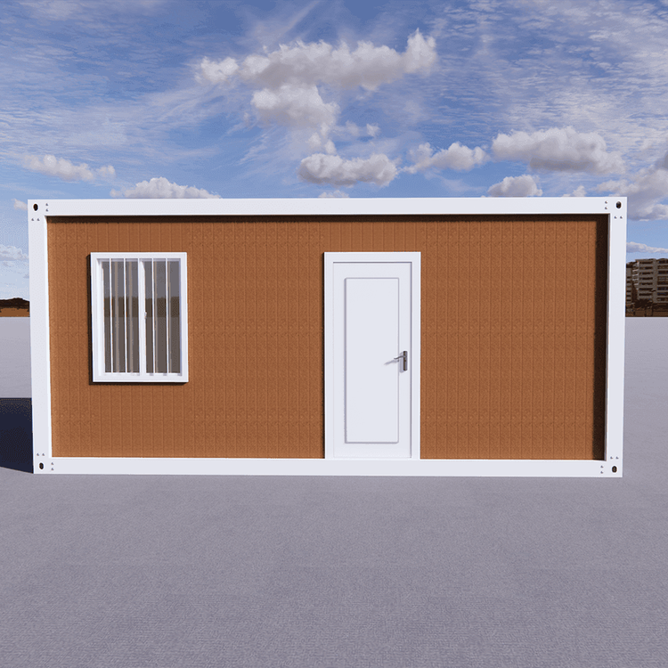
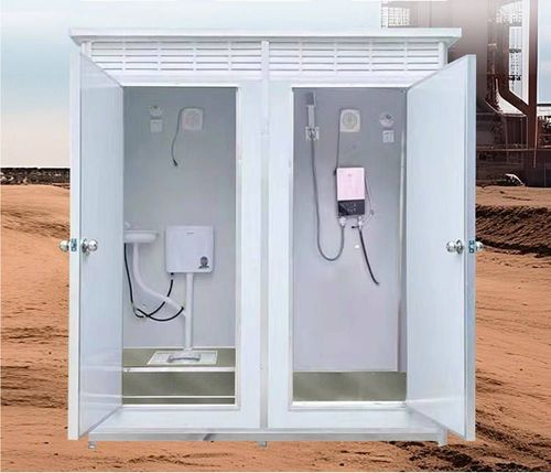
The finished mobile toilet construction drawing is a guiding document that involves coordination across multiple disciplines. Its core content includes six major modules: overall layout, structural system, water supply and drainage, electrical system, internal facilities, and environmental protection and safety design.

1. Overall Layout Design
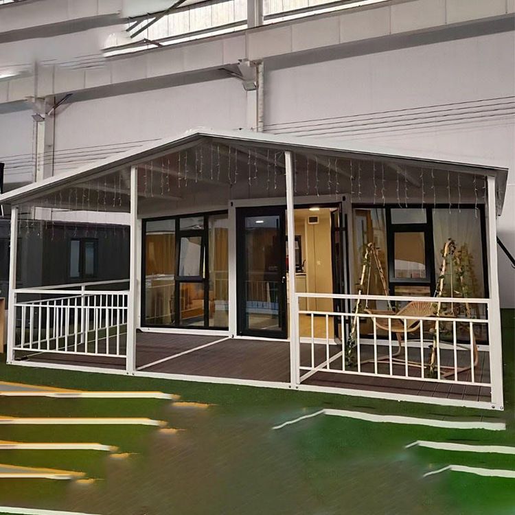
The layout form should be determined based on the site terrain, pedestrian traffic, and surrounding environment. Common types include single-unit, multi-unit combination, and barrier-free dedicated styles. The floor plan should indicate the positions of toilet stalls, aisle width (usually ≥90cm), entrance/exit directions, and overall dimensions (length, width, height) to ensure transportation and installation meet standards. Ventilation is achieved through top vents or side windows, while lighting relies on natural light sources supplemented by artificial lighting.
2. Structural System Details
The frame is made of lightweight metal materials (such as aluminum alloy). The drawing should indicate the connection method (e.g., bolt fixation) and fixation positions of columns and beams. The walls consist of inner and outer layers: the outer layer is a waterproof panel (such as PVC board), and the inner layer is an insulation layer (such as polystyrene). The thickness and installation sequence should be indicated. The roof design should specify the slope (usually 3%-5%), drainage trough positions, and rainproof measures (such as waterproof membranes). The sectional view should show the joint details with the walls (e.g., sealant treatment).
3. Water Supply and Drainage System Planning
For the water supply part, draw the pipe routing, valve positions, and water tank installation points. Indicate the pipe material specifications (such as PPR pipes) and connection methods (hoses or hot-melt connections), and explain anti-freezing measures (such as insulation sleeves). The drainage system includes the layout of toilet waste pipes, septic tanks, or collection tanks. Use arrows to indicate the water flow direction, and indicate the pipe slope (≥2%) and capacity. The installation of water-saving devices (such as low-flow flush valves) should be explained separately.
4. Electrical System Design
If lighting or ventilation equipment is required, draw the circuit wiring diagram, indicating the power access points, switch/socket positions, and wire specifications (such as BV-2.5mm²). The protection level should meet environmental requirements (such as waterproof cables IP44). For lighting, specify the lamp type (LED lights), installation height (such as 2.2-2.5m), and emergency lighting configuration (such as backup battery power supply for ≥30 minutes). The circuits for exhaust fans or heaters should be indicated separately.
5. Internal Facilities and Decoration
The fixed positions and installation methods of components such as toilets, sinks, and mirrors should be indicated (e.g., an enlarged view of the sink support structure). For wall materials, prioritize non-slip tiles or composite materials. The floor should indicate non-slip treatment (such as non-slip tiles or coatings). The positions of auxiliary facilities (hooks, paper towel holders, trash cans) should be reasonably planned to ensure convenience of use.
6. Environmental Protection and Safety Features
Environmental protection design includes the installation positions of solar panels, battery storage units, and rainwater collection devices (for flushing or cleaning). In terms of safety, indicate the application of fire-resistant materials (such as Class A fire-resistant panels for walls). The electrical system should be equipped with leakage protection devices to ensure safety during use.