Back to blog
Article
Container House Transportation and Installation Diagram
Admin September 16, 2026
The transportation and installation diagram of container houses typically includes schematic diagrams and descriptions of key steps such as bottom frame installation, wall installation, and floor laying. The following provides detailed information in combination with specific cases:

Bottom Frame Installation
- Connection of the bottom corner and the bottom beam: On a flat ground or a workbench, connect the bottom corner of the container to the bottom beam using hexagon socket bolts, but do not tighten them temporarily. Tighten the bolts after alignment (ensuring that the diagonal difference of the bottom frame is ≤ 3mm).
- Installation of π-shaped secondary beams: Install the π-shaped secondary beams according to the positions of the positioning holes on the long beams, and fix them with m5.519 self-tapping screws. At the same time, the top of the π-shaped secondary beams and the bottom beams should be fixed with st4.816 round-head self-drilling screws.
Wall Installation (Taking the foldable type as an example)
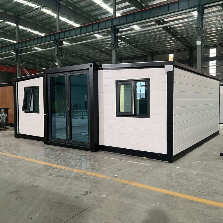
- Lifting and unfolding of the main frame: After checking the stability of the steel wire ropes, lift the main frame and unfold it smoothly. Place a support rod in the middle of the container to keep it stable.
- Pushing and fastening of the walls: Push open one wall and tighten it with fastening screws, then push open the other wall with doors and windows and fix it with fastening screws in the same way.
Floor Laying
- Laying of the floor base plate: Lay the floor base plate (such as magnesium oxide board) along the 6-meter direction. The base plates at both ends have been pre-punched and need to be cut at the marked chalk lines.
- Marking and laying of the floor: Make marks at the center line of the π-shaped beams, and start laying the floor from one end so that the joint of the two floor panels coincides with the center line of the π-shaped beams. After the floor is laid, snap chalk lines on the floor according to the center line marks of the π-shaped beams (two chalk lines are required at the joint, each deviating 20mm from the center line), and fix the floor along the chalk lines with st4.2*38 cross-head flat-tail screws, with a nail spacing of 300-350mm.
- Floor treatment: Sand the entire floor, especially the panel joints, apply PVC special floor adhesive, wait for 10-15 minutes, then lay the floor covering, and expel the air between the floor covering and the base plate. If possible, perform welding treatment on the joints of the floor covering.