Renovation Construction Drawings for Container Houses
The renovation construction drawings for a 20-foot international standard container house include CAD drawings for plans, elevations, and sections, as well as 3D modeling for water and electricity routing, meeting construction requirements. The following provides an explanation from three aspects: drawing content, design details, and construction applications.

I. Core Content of CAD Drawings for Plans, Elevations, and Sections
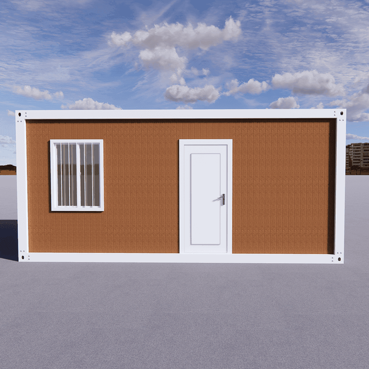
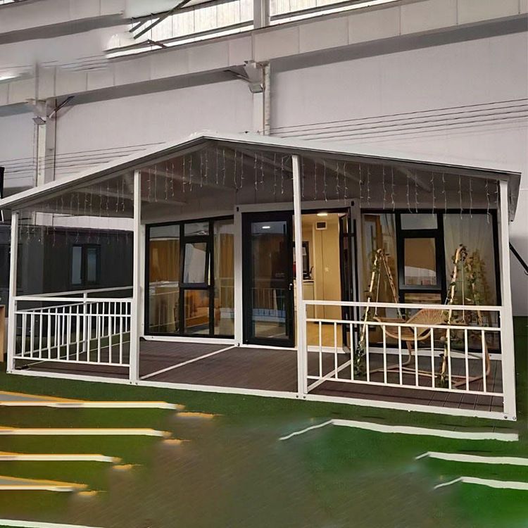
Plans, elevations, and section drawings are fundamental design documents for container house renovation, encompassing plan views, elevation views, and sectional views. The plan view clearly marks the positions of doors and windows, typically using standard dimensions (e.g., door width of 0.9-1.2 meters, window width of 1.2-1.5 meters) to ensure compliance with ergonomic requirements and ventilation and lighting needs. The elevation view displays details of the container's exterior renovation, such as the installation methods for adding insulation layers, decorative panels, or sunshading components. The sectional view reveals the internal space's layered design, such as the structural reinforcement plan for a second-floor loft, which requires welding angle steel or channel steel to form a supporting framework to ensure load safety. The drawings strictly adhere to the dimensions of international standard containers (length: 6058mm, width: 2438mm, height: 2591mm) to ensure compatibility with transportation and lifting equipment after renovation.
II. Key Designs for Structural Reinforcement and Water and Electricity Routing
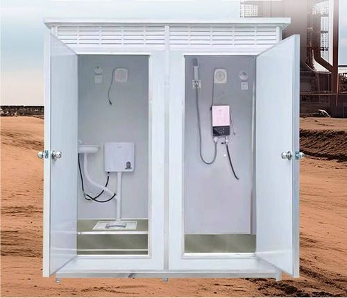
Structural reinforcement is a core aspect of container renovation. Since the original container design is only intended to bear cargo loads, it is necessary to enhance living safety by adding horizontal and vertical reinforcement components. For example, vertical columns are added at the corners and midpoints of the container, welded using Q235 steel with a spacing not exceeding 1.2 meters; horizontal trusses are added at the top to prevent deformation caused by snow accumulation or human activity. The design of water and electricity routing must coordinate with structural reinforcement: electrical circuits are concealed using PVC pipes, avoiding structural welds; water pipes use PPR pipes, arranged along the inner sides of walls with reserved maintenance access; the drainage system requires a slope (≥2%) to ensure smooth sewage discharge. 3D modeling technology can visually display the spatial relationships between water and electricity pipelines and structural components, avoiding construction conflicts.
III. Application Value and Implementation Points of Construction Drawings
Construction drawings serve as the 'technical language' guiding on-site operations. Construction personnel must follow the drawings to complete the following steps:
- Foundation Treatment: Pour a concrete foundation or install a steel structural ground beam according to the ground elevation marked in the sectional view to ensure the container is placed horizontally;
- Structural Renovation: Cut door and window openings according to the plan view, weld reinforcement components, and perform anti-corrosion treatment (e.g., spraying anti-rust paint);
- Pipeline Embedding: Refer to the water and electricity routing diagram to cut grooves in walls and floors, lay pipelines, and secure them;
- Decoration and Finishing: After installing insulation layers and decorative panels, adjust the opening directions of doors and windows and the positions of hardware components according to the elevation view.
3D modeling can simulate the construction process in advance, identify potential issues (e.g., pipeline collisions), reduce rework rates, and ensure 'one-time success'.