Interior Construction Drawings of Container Houses
Interior construction drawings of container houses typically include detailed internal structural designs, spatial divisions, and functional zoning diagrams. Some drawings explicitly indicate material specifications and construction nodes, making them directly usable for guiding construction.

1. Basic Structure and Structural Design
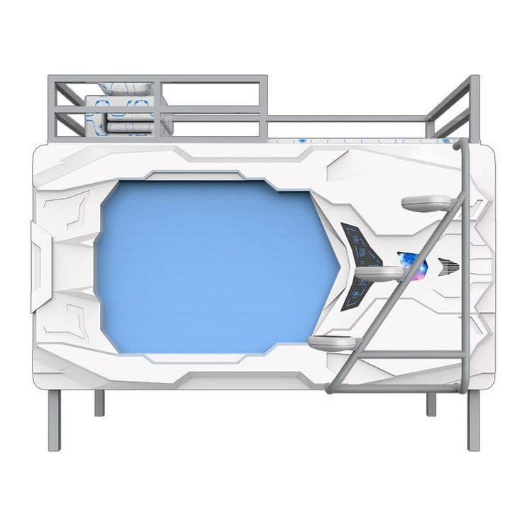
The interior construction drawings of container houses must first clarify the basic structure, such as the laying of checkered steel plates on the ground floor and the thickness of the insulation layers on the roof and walls. Taking the CAD construction drawings for the structural design of container-style houses as an example, they include floor plans and elevation views of the upper and lower bunks in the project manager's office, as well as detailed drawings of connections between angle steel and I-beams, and between exterior wall panels and internal partition walls. These drawings, through sectional or partial enlarged views, provide detailed annotations on steel specifications (such as angle steel dimensions and I-beam models), connection methods (welding or bolt fixation), and insulation materials (such as polystyrene boards or rock wool boards), ensuring structural safety and compliance with thermal performance standards.
2. Spatial Division and Functional Layout
Interior construction drawings must clearly delineate functional areas, such as bedrooms, bathrooms, and kitchens. In the CAD construction drawings for the architectural design of a container house project, the design of the staircase and platform for the second floor of a 3×6-meter container house exported to Japan is illustrated through a combination of floor plans and elevation views, indicating the height of stair treads, the load-bearing structure of the platform, and its connection to the container body. The prefabricated container dormitory project uses a three-story floor plan to annotate the functional zoning of each floor, such as a public activity area on the first floor, dormitories on the second floor, and administrative offices on the third floor, and specifies the container combination method (such as horizontal or vertical stacking).
3. Facility Installation and Detailed Nodes
Construction drawings must include installation details for key facilities, such as water and electricity pipelines, doors and windows, and drainage systems. The detailed drawing of the corner downspout installation in the CAD construction drawings for the architectural design of a container house project annotates the connection method between the downspout and the corner of the container body (such as using waterproof sealant or metal brackets for fixation). The complete set of CAD construction drawings for a creative container sales office annotates the location of floor drains, drainage slopes, and pipeline routes through a basic floor plan to ensure smooth drainage. Additionally, some drawings indicate the types of doors and windows (such as triple-glazed windows) and their opening methods to enhance sound insulation and thermal insulation performance.
4. Interior Design References for Special Cases
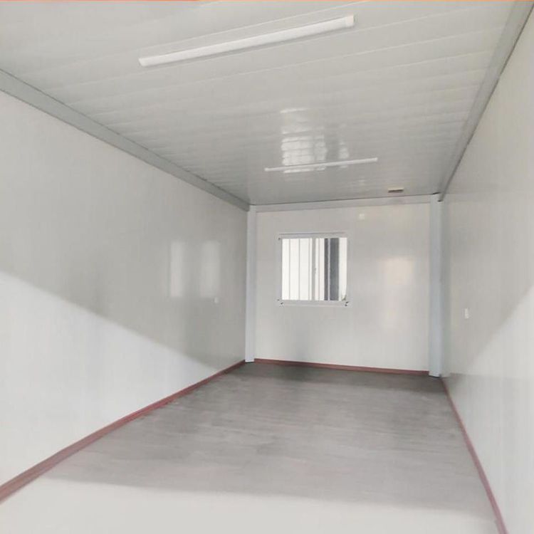
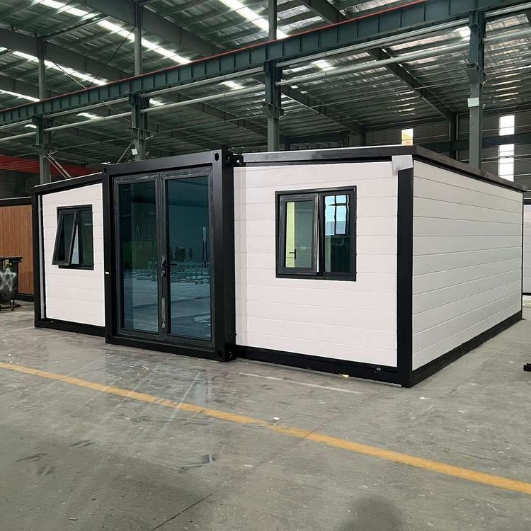
If drawings are lacking, design inspiration can be obtained through textual descriptions. For example, in the case of two containers transformed into a scenic luxury mansion, they are spliced to form a 100-square-meter single-story space with an open-plan living/dining/kitchen area, clearly divided bedrooms and bathrooms, and a bathroom equipped with a bathtub. The adoption of modern facilities such as internal insulation layers (to enhance winter comfort), solar systems (to reduce energy consumption), and triple-glazed windows (to enhance sound insulation) provides functional and comfortable design references for the interior design of container houses.